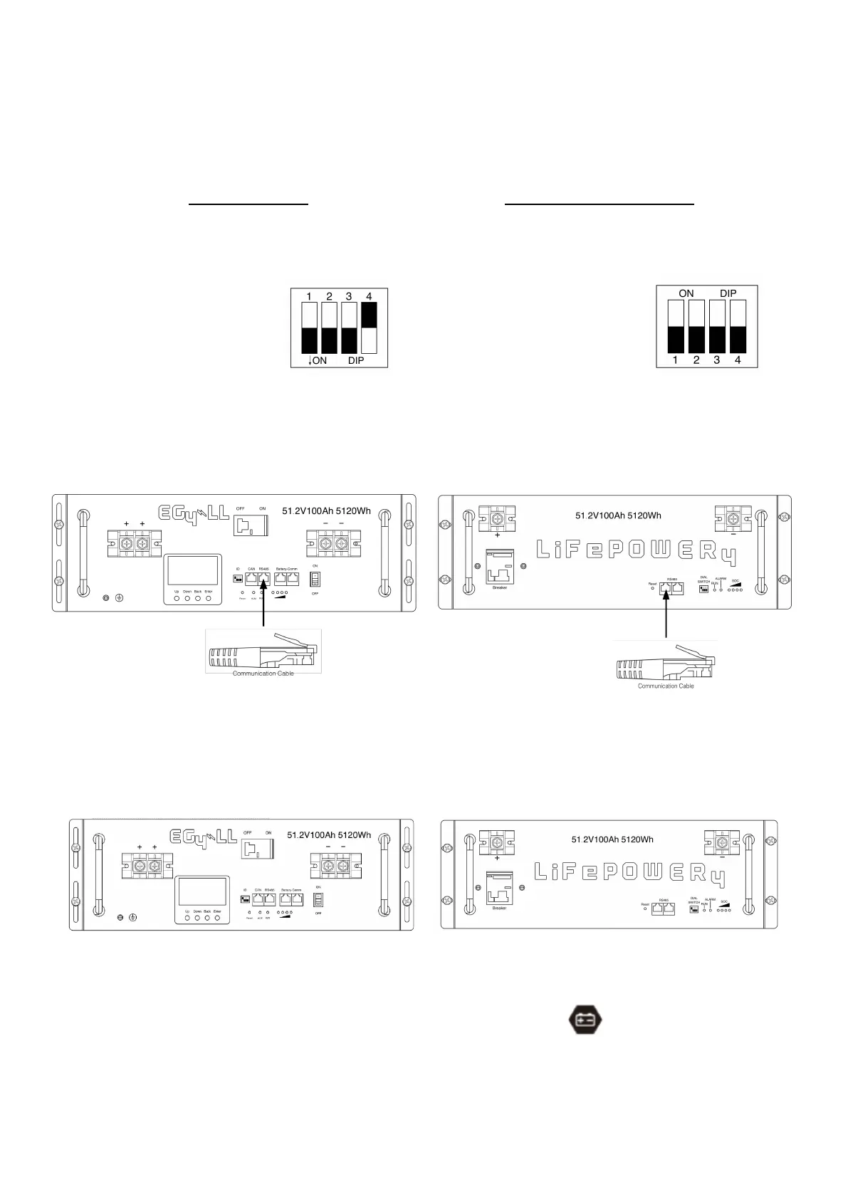
Settings for EG4 Lithium Batteries- Master/Slave
1). Dip Switch: There are 4 Dip Switches which set different baud rates and battery
group addresses. If switch position is turned to the “OFF” position, it means “0”. If
switch position is turned to the “ON” position, it means “1”.
• Dip 1, 2, and 3 are in the
“ON” position
*on = down
• Dip 4 is in the "OFF"
position
*off = up
• The 1-3 "ON" & 4 "OFF"
configuration is to indicate
Master battery status and
is reserved for
communications with the
inverter.
• A Max of 16 batteries can
communicate in a single
battery bank using
different dipswitch
addresses.
EG4-LL Battery
• Dip 1, 2, 3, and 4 are in the
“OFF” position
*off = down
• The ALL "OFF" position is to
indicate the Master battery
status and is reserved for
communications with the
inverter
• A Max of 16 batteries can
communicate in a single
battery bank.
EG4-LifePower4 Battery
Please Note: If you change the dipswitches, you must power cycle the batteries
for the BMS to recognize the new dipswitch address.
2). Installation
Step 1. Use the RS485 cable to connect the inverter and Lithium battery as Fig 1.
Step 2. Switch on the battery breaker/s.
Step 3. Turn on the inverter.
Step 4. Select battery type as “EG4” in LCD program 5 for the Master inverter. For other paralleled
inverters, set to "USE".
If communication between the inverter and battery is successful, the battery icon
on LCD display will flash
NOTE:
For EG4-LL ensure the red power switch is set to "ON" as well as the breaker.
NOTE:
Even with the EG4 batteries having built-in breakers, a minimum 150A in line breaker is required, and a 200A
in line breaker is recommended.
NOTE:
Refer to each battery manual for setting master and follower battery address settings.