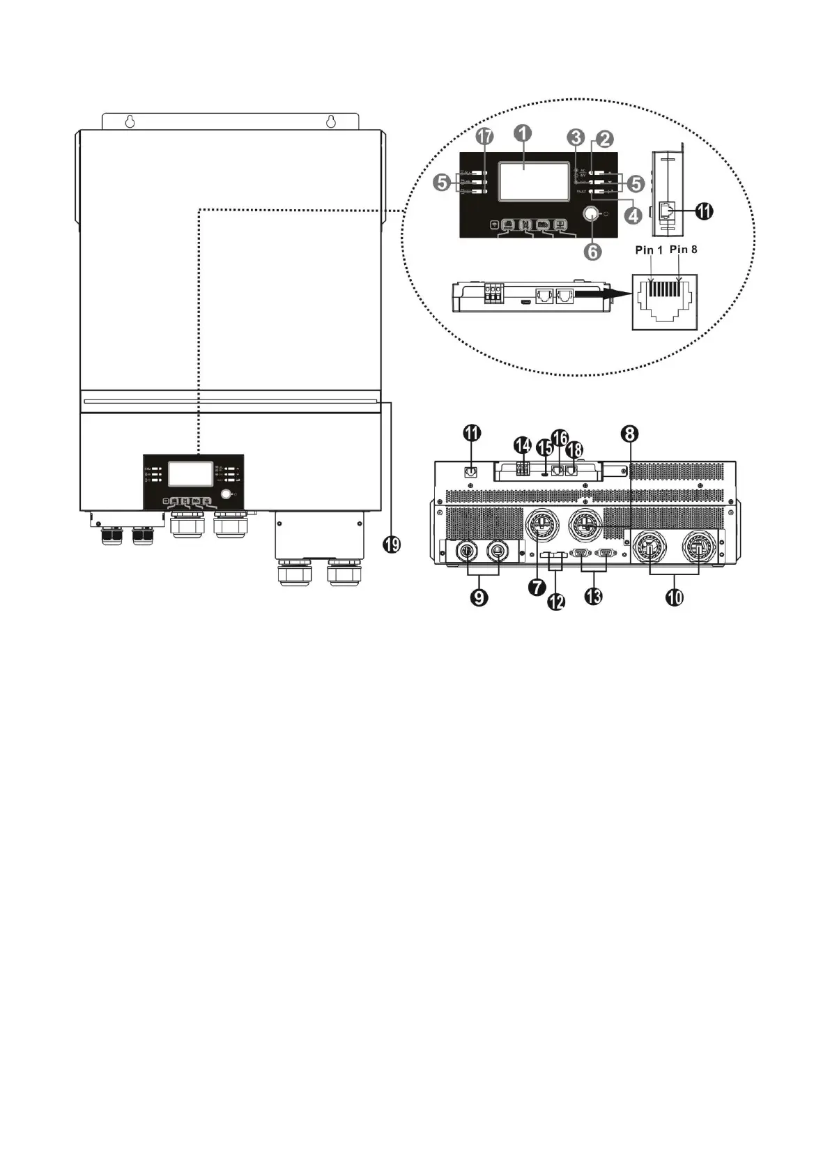
1. LCD display
2. Status indicator
3. Charging indicator
4. Fault indicator
5. Function buttons
6. Power on/off switch
7. AC input connectors
8. AC output connectors (Load connection)
9. PV terminal
10. Battery connectors
11. Remote LCD module communication
12. Current sharing
port
13. Parallel communication port
14. Dry contact
15. OTG-USB port as USB communication port and USB
function port
16. BMS communication port: CAN, RS-485 or RS-232
17. Output source indicators (refer to OPERATION/Operation
and Display Panel section for details) and USB function
setting reminder (refer to OPERATION/Function Setting for
the details)
18. RS-232 communication port for firmware updates from a
PC
19. RGB LED bar (refer to LCD Setting section for the details)
Port
Product Overview
Installation Note: The EG4 6.5KW unit is a parallel capable model. For parallel 120V, 240V Split-phase, or
3-phase installation diagrams and instructions, please check the
Parallel Connections
and
Commissioning
sections of the manual for further details.