Parallel Inverter Connections
1. Introduction
This model of inverter is a 120V Single-phase unit able to operate in parallel with multiple other units. The
parallel function can be used to support multiple electrical system types, including multi-inverter Single-phase,
240 Split-phase, or 3-phase.
ATTENTION: Carefully review the paralleling requirements, specifically the current sharing cable connection
tables and parallel settings.
Battery Bank Considerations:
When designing the system, ensure the battery bank of the system is able to support both the potential max
load/s and constant load. Multiple inverters meeting a high load requirement with an undersized battery bank
will result in a system shutdown and potentially damage equipment.
Recommended Battery Sizing:
Inverters per System 2 3 4 5 6
Battery Capacity (48V) 200AH 300AH 400AH 600AH 600AH
WARNING! All inverters of a system must share the same battery bank. Ensure all batteries are connected to
common bus bars, with equal cable lengths between both the batteries/bus and inverter/bus connections.
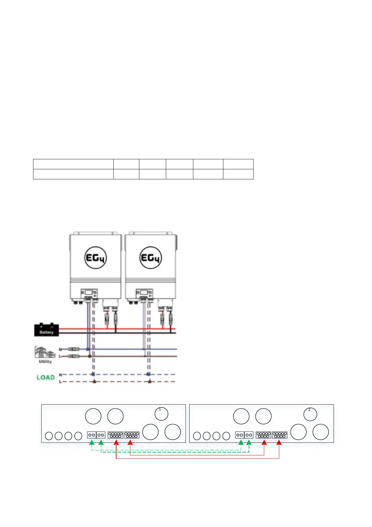
2. Parallel Connections for 120V Single-phase:
Communication Connection
2
1
AC connections are the same for units 3-6.
• Inverter 1 Port A → Inverter 2 Port A
• Inverter 1 Port B → Inverter 2 Port B
Current Sharing Cables - configuration will be
noted on each diagram with dashed lines (green
when printed in color) in the following format:
• Inverter X Port A → Inverter X Port A
• Inverter X Port B → Inverter X Port B
WARNING: Damage to the inverters can occur
if current sharing cables are incorrectly
installed.
See Split-phase and 3-phase communication
connection guides for specifics.