AC Input/Output Connections
CAUTION!! Install a breaker at the source of the AC input power source per requirements of authority
having jurisdiction. Ensure the AC source circuit is properly rated for the inverter/charger load
specification.
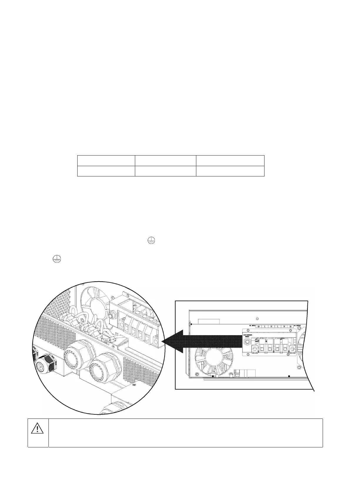
CAUTION!! There are two terminal blocks with “IN” and “OUT” markings. Do NOT reverse the input and
output connections. Ensure Line, Neutral, and Ground are wired to the correct terminals.
WARNING! All wiring must be performed by a qualified personnel.
WARNING! It is very important for system safety and efficient operation to use appropriate cable for AC
input connection. To reduce risk of injury and equipment damage, use properly sized cables according to local
jurisdiction and electrical code/requirements.
Suggested cable requirement for AC wires
Model Gauge Torque Value
6.5KW 4 AWG Max 1.4~ 1.6Nm
Follow the below steps to connect the AC input and output:
1. Before making AC input/output connection, be all power sources are off.
2. Remove 10mm (3/8in) wire insulation from the ground wires. Remove 7mm (~1/4in) of wire insulation
from the Line and Neutral conductors. Ensure no conductor is exposed beyond terminal block, paying
special attention to possible stray wire strands.
3. Fix two cable glands into input and output sides.
4. Insert AC input wires according to polarities indicated on terminal block and tighten the terminal screws. Be
sure to connect PE protective conductor ( ) first.
L→LINE(Black for Line 1)(Red for Line 2 in 120/240 split-phase configuration)
N→Neutral (White or Gray)
WARNING:
Ensure all AC sources remain off and all loads are turned off at the breakers before continuing with the
wiring process. Confirm AC source is off with multi-meter or non-contact voltage pen/tester.
Ground (Green or Green with Yellow stripe)