i. Remove 10 mm (3/8in) of insulation for positive
and negative conductors.
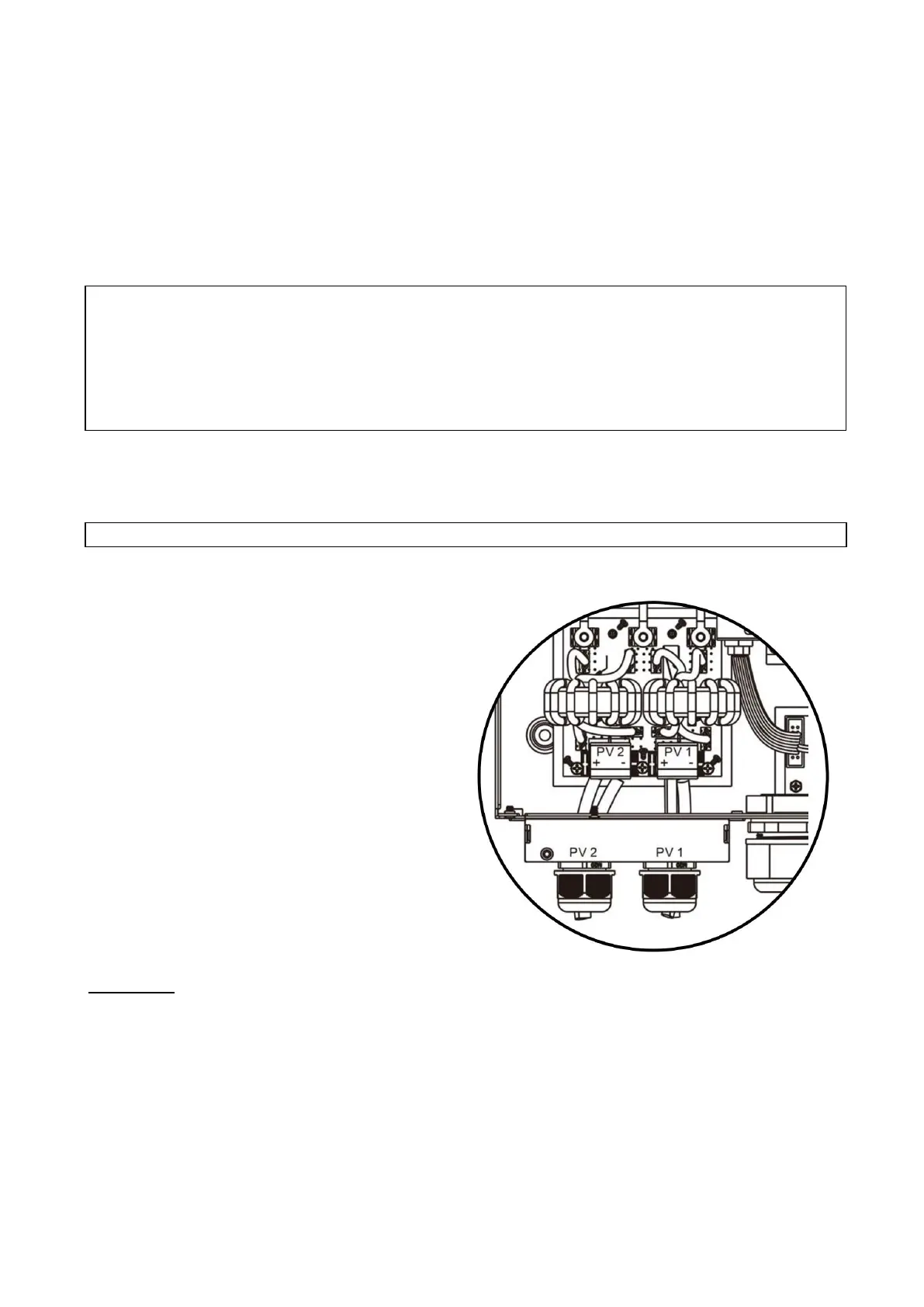
ii. Check correct polarity of connection cable from
PV modules and PV input connectors at the
disconnect. Connect positive pole (+) of
connection cable to positive pole (+) of PV input
connector. Connect negative pole (-) of connection
cable to negative pole (-) of PV input connector.
Step 3: Step 3: Make sure the wires are fully
inserted and the terminals are torqued to spec.
CAUTION! Ensure no wire strands are exposed
outside of the terminals blocks. No copper of the
conductions should be visible.
It is highly recommended to use red PV wire for
positive and black PV wire for negative to
reduce risk of reversing polarity in the system.
PV Connections
CAUTION: Before connecting PV modules/strings, install separate DC circuit breakers or a means of
disconnect paired with properly sized fuses between inverter and PV array/s. DO NOT work with or
connect live PV conductors to the unit. Ensure all exposed conductors are safely disconnected from
the power source.
NOTE: Use a 600VDC/30A rate circuit breaker. DC rated breakers must be used. The over voltage
category of the PV input is II. Please follow the steps below to implement PV module connection.
Step 1: Check the voltage of the PV modules/strings; ensure open circuit voltage (Voc) is designed to
never exceed the units rating (500V DC). This unit is equipped with two PV MPPT string inputs. Ensure
the maximum operating amperage (Imp) of each PV input is 18A or less. When using Rapid Shut Down
equipment refer to the RSS manufacturer's specifications for per-device and per-string ratings.
Step 2: Disconnect the circuit breaker and switch off the DC disconnect. Follow wiring process below.
CAUTION: Exceeding the maximum input voltage can destroy the unit! Check the system before wire connections.
WARNING: Because the inverter/charger is non-isolated, only three types of PV modules are
acceptable: monocrystalline and polycrystalline with class A-rated and CIGS modules.
To avoid malfunction, do not connect PV modules with possible current leakage. For example, grounded
PV modules will cause current leakage to the inverter. When using CIGS modules, please be sure NOT to
ground.
CAUTION: It is required to use a PV surge protection device. Damage to the inverter can occur from
surges such as lightning or short circuiting.
WARNING!
Open circuit Voltage (Voc of PV strings must not exceed the maximum PV array open circuit voltage of the
inverter. Check for environmental impacts on Voc, such as temperature in accordance to the module
manufacturers data sheet and reliable weather data for the installation location.
Voltage at Maximum Power (Vmp) of PV strings must be higher than the start-up voltage.