INSTALLATION
10/2022 33 NP-DK50 2V-A-4_10-2022-AD
Connect the cabinet pressure gauge to the compressor per Chapter 11.2.
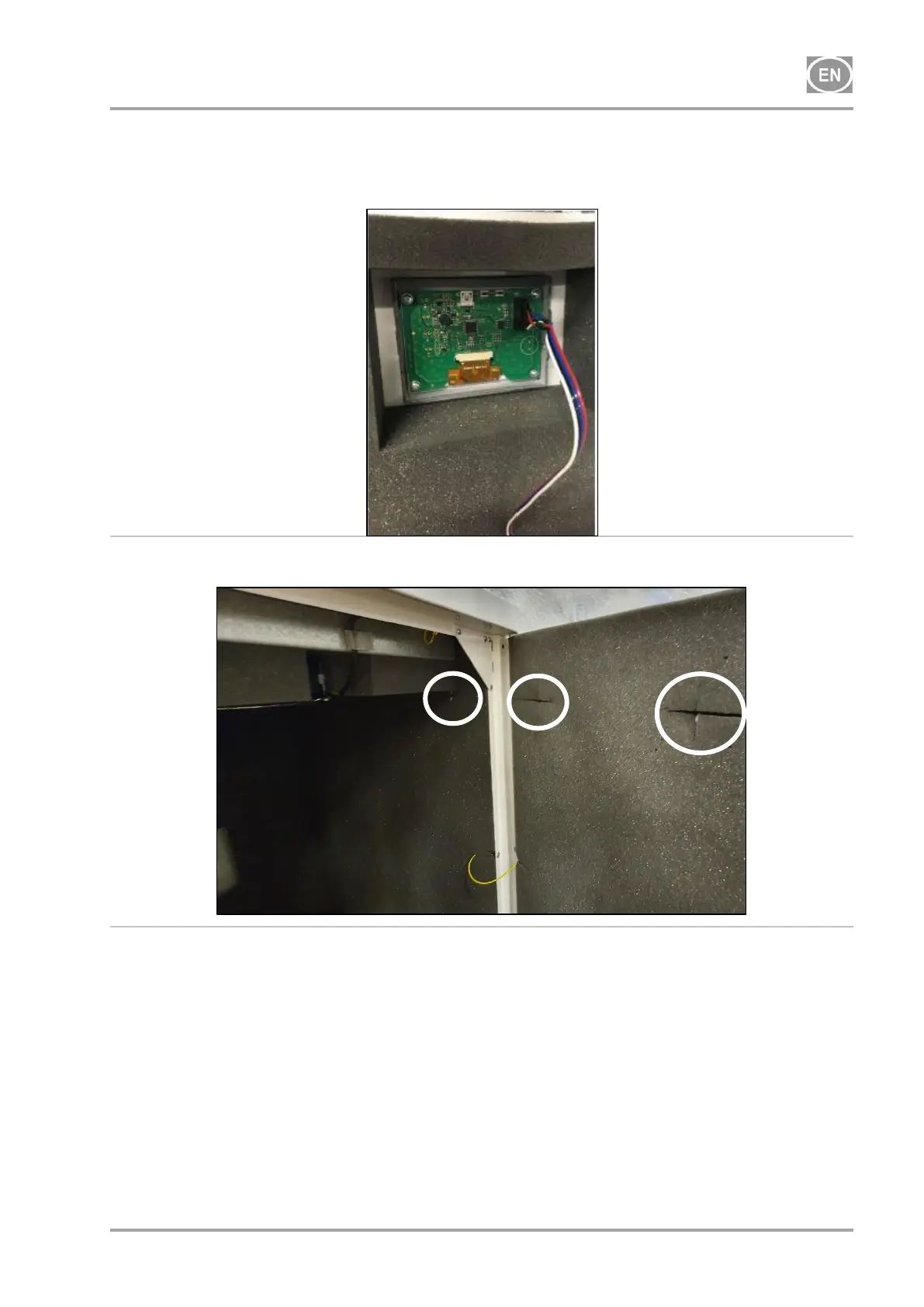
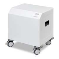
Connect the display in the front door of the cabinet (Fig. 15), and secure the cord to the
display in the clamps (Fig. 16).
Fig. 15: Connecting the display connector
Fig. 16: Position of the clamps in the cabinet
14. COMMISSIONING
Check if all fixing elements used during transport have been removed.
Check correct connection of compressed air (see chapter 11).
Check correct connection to the mains (see chapter 12)
Check position of the circuit breaker switch, it must be in position „I“. If it is in position „0“,
turn the switch (2) to position „I“ (Fig. 17)
On compressor in the cabinet, switch the switch (5) on the front side of the cabinet to position
„I“, the green light indicates the device status in operation. (Fig. 17).
Check connection of the cabinet manometer hose to the pneumatic block of the compressor.