INSTALLATION
NP-DK50 2V-A-4_10-2022-AD 34 10/2022
Check the connection of the display at the front door of the cabinet.
Set the language, time and drying mode (see chap. 19.2, 19.3) on the compressor display
The compressor is not equipped with a backup power supply.
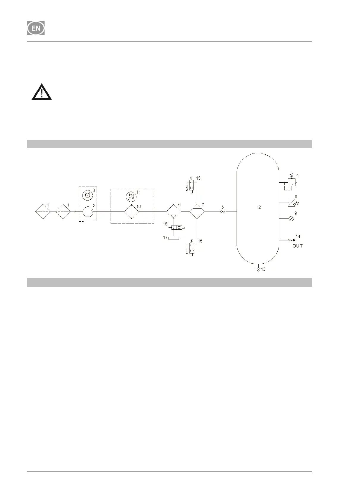
15. PNEUMATIC AND ELECTRICAL DIAGRAMS
15.1. Pneumatic diagram
Description to pneumatic diagrams:
1 Inlet filter
2 Air pump
3 Fan
4 Safety valve
5 Non-return valve
6 Condensate searator
7 Dryer
8 Pressure switch
9 Pressure gauge
10 Cooler
11 Cooler fan
12 Air tank
13 Condensate drain valve
14 Outlet valve
15 Solenoid valve – regeneration
16 Solenoid valve – condensate drain
17 Condensate collection vessel