(
r
(
Interface Circuitry
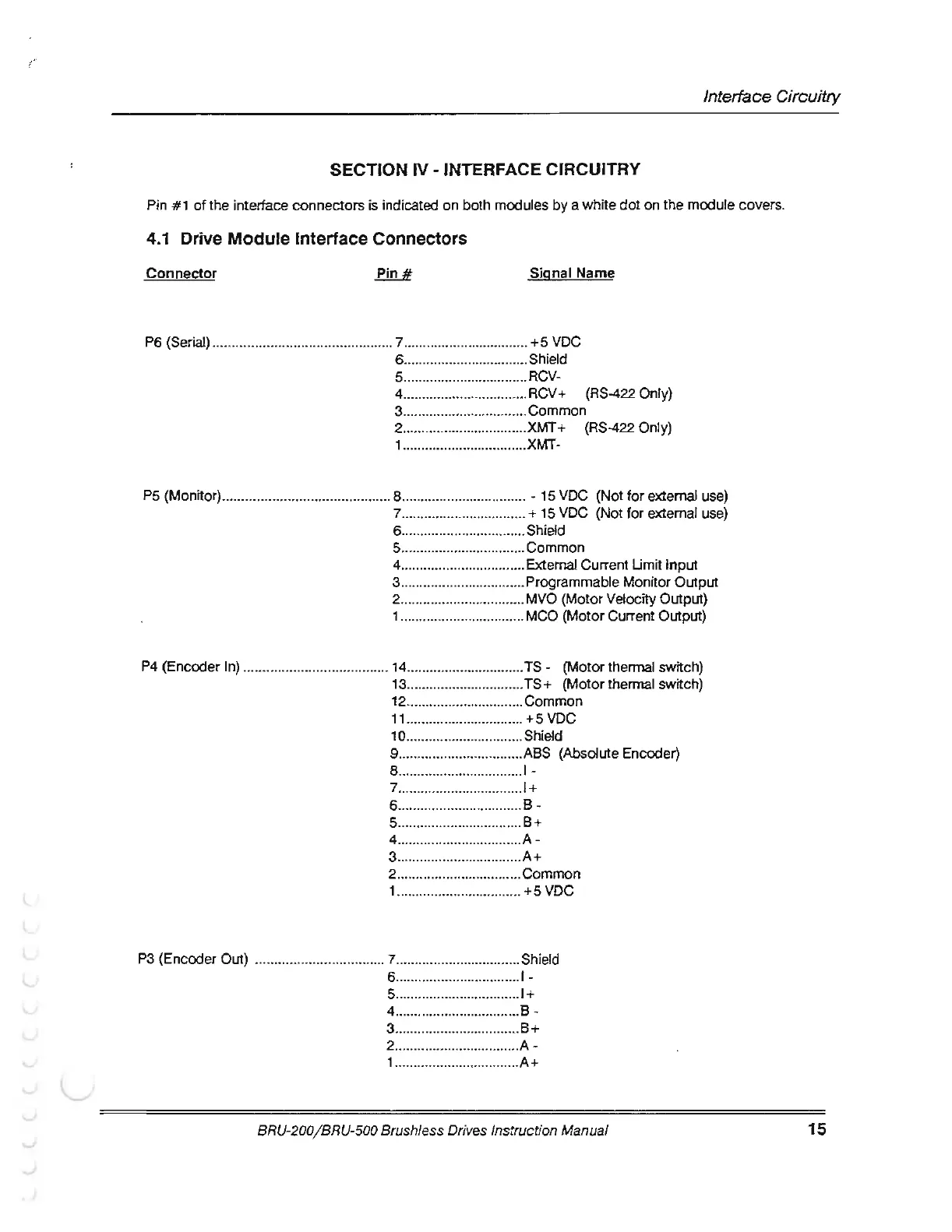
SECTION IV • INTERFACE CIRCUITRY
Pin
#1
of
the
interface connectors is indicated
on
both modules
by
a white
dot
on
the
module covers.
4.1
Drive Module Interface Connectors
Connector
Signal
Name
P6 (Serial) ............................................... 7 ....
..
........................... + 5 VDC
6 ................................. Shield
5 ................
....
............. RCV-
4 .........................
..
...... RCV+ (RS-422 Only)
3 ................................. Common
2 ................................
J<MT
+ (RS-422 Only)
1 .................................
XMT-
P5 (Monitor) ....................
..
....... ............... 8 ................................. - 15 VDC (Not for external use)
? ................................. + 15 VDC (Not
for
external use)
6 ................................. Shield
5 ................................. Common
4 ...
..
............................ External Current Umit
Input
3 ................................. Programmable Monitor
Output
2 ................................. MVO (Motor Velocity Output)
1 ................................. MCO (Motor Current Output)
P4
(Encoder In) ...................................... 14 ...............................
TS-
(Motor thermal switch)
13
...............................
TS+
(Motor
thermal switch)
12 ............................... Common
11
...............................
+5
VDC
10 .......................
..
...... Shield
9 .................................
A8S
(Absolute Encoder)
8 .................................
1-
7 .................................
1+
6
..
...............................
8-
5 ....... ..........................
8+
4 ..................
..
.............
A-
3
..
.......... .....................
A+
2 .........
..
.
..
....
....
.....
..
.... Common
1 ..................
..
...........
..
+5
VDC
P3
(Encoder Out) ....................
..
............ 7 ................................. Shield
6 ................................. 1-
5 ..............................
...
1+
4 ......
..
......................
..
. 8 -
3 ............ .....................
8+
2
..
............................... A -
1
..
............................... A +
BRU-200/BRU-500 Brushless Drives In
str
uction Manual
15