Interface Circuitry
16
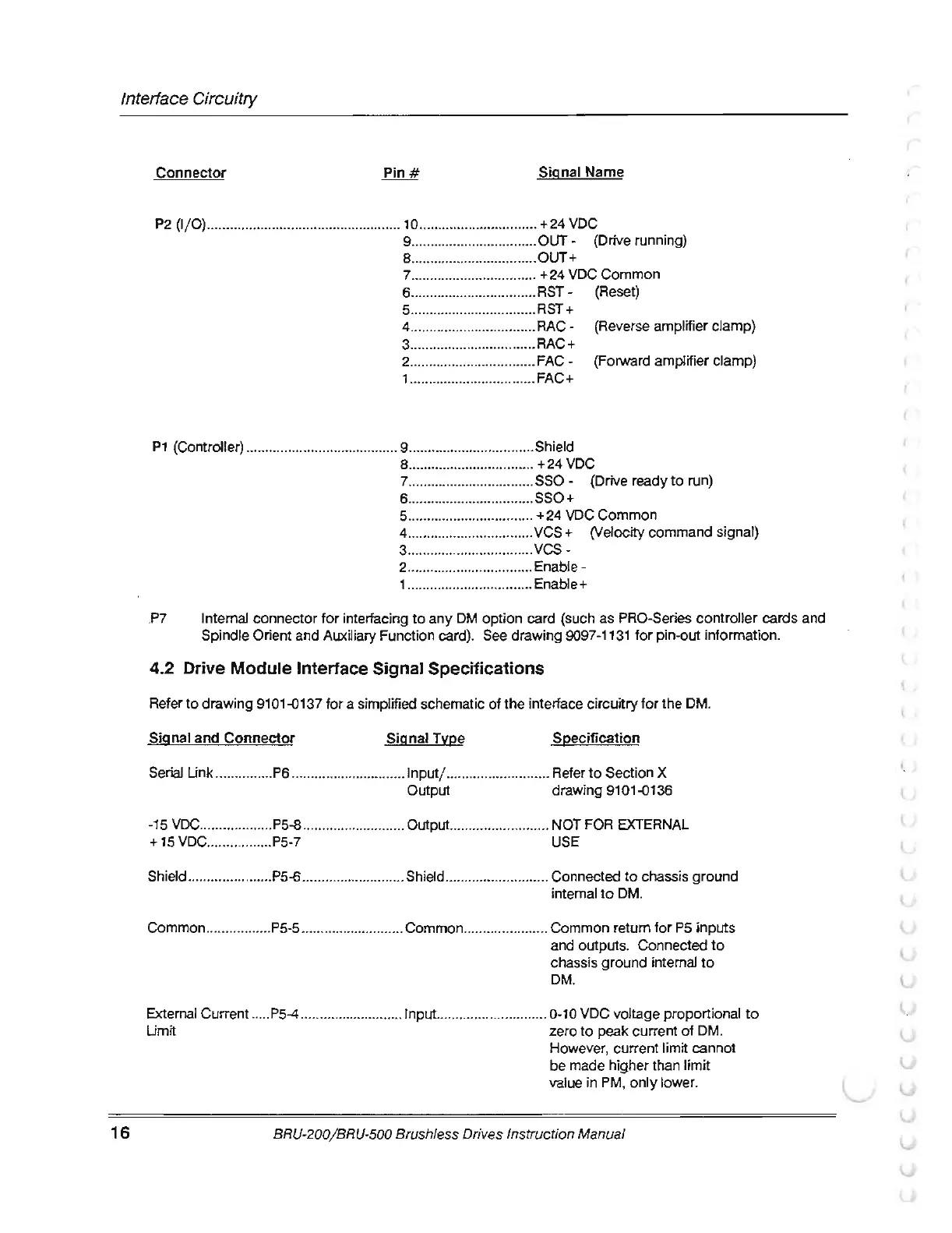
Connector
Signal Name
P2
(1
/
0)
......
..
..............................
..
...........
10
............................... +24
VDC
9 .................................
0UT-
(Drive running)
S ................................. OUT+
7 ....
..
........................
..
.
+24
VDC Common
6 .................................
RST
- (Reset)
5 ..........
..
.....................
RST
+
4 .......................
..
........
RAC
- (Reverse amplifier clamp)
3 ................................. RAC+
2 ...................
..
......
..
....
FAC-
(Forward amplifier clamp)
1 ............................
..
... FAC+
P1
(Controller) ....................................
....
9 ................................. Shield
8 .................................
+24
VDC
7 .................................
SSO-
(Drive ready
to
run)
6 ................................. SSO+
5 ................................. + 24 VDC Common
4 ...............................
..
VCS + (Velocity command signal)
3 ................................. vcs-
2 .............
....
................ Enable -
1 ................................. Enable+
.P7
Internal connector for interfacing
to
any OM option card (such as PRO-Series controller cards and
Spindle Orient and Auxiliary Function card). See drawing
9097-1131
for pin-out information.
4.2 Drive Module Interface Signal Specifications
Refer to drawing 9101-0137 for a simplified schematic
of
the interface circuitry for the
OM
.
Signal and
Connector
SignaiTvpe
Specification
Serial Unk ...............
P6
.............................. 1 nputj ...........................
Refer
to
Section X
Output drawing 9101-0136
-15
VDC
................... P5-8 .......................
..
..
0utput
.......................... NOT FOR EXTERNAL
+15
VDC
.
..
.............. P5-7
USE
Shield ...................... P5-6 ...........................
Sh
ield .....................
..
.... Connected
to
chassis ground
internal
to
OM
.
Common ................. P5-5 ........................... Common .................
...
..
Common retum for
P5
inputs
and outputs. Connected
to
chassis ground internal
to
OM
.
External Current ..... P5-4 ........................... Input ............................. 0-10 VDC voltage proportional
to
Umit zero
to
peak current
of
OM.
However, current limit cannot
be made higher than limit
value in
PM,
only lower.
BRU-200
/B
RU-500 Brushless Drives Instruction Manual
(