Optional Accessories
48
6.) The VCS test points are used
to
monitor the
VCS
command
to
the Drive Module.
7.) The programmable monitor test points may be used to monitor the signal selected as the Monitor
signal using a serial terminaL Information
on
the choice of signals that can be output
to
these test
points is shown
by
moving the cursor
to
the Monitor line
on
the serial terminal Setup page.
8.) The MVO test points are used
to
monitor the Motor Velocity Output (tachometer) from the Drive
Module.
9.) The
MCO test points are used
to
monitor the Motor Current Output (current command) from the
Drive Module.
10
.) The current limit switch sets the peak current limit
to
25
,
50
,
or
100%
of the Drive Module peak
current rating.
11.) The RUN/RESET switch is used to reset the Drive Module fault circuits by momentarily setting
to
RESET
and then
to
RUN
.
12.) The
OUT1
LED
is
ON
when the contacts
of
the OUT relay
are
closed in the Drive Module.
13
.) The SSO
LED
is OFF when there
is
either a Drive Module fault
or
the reset switch is activated.
NOTE: The
RED
test points are + (plus). and the BLACK test points
are-
(minus) . Bl
ack
test points
PROG MONITOR,
MVO,
MCO,
(and
VCS
when
SELECT
is set
to
VCS
dial) are connected
to
signal COMMON on the Drive Module.
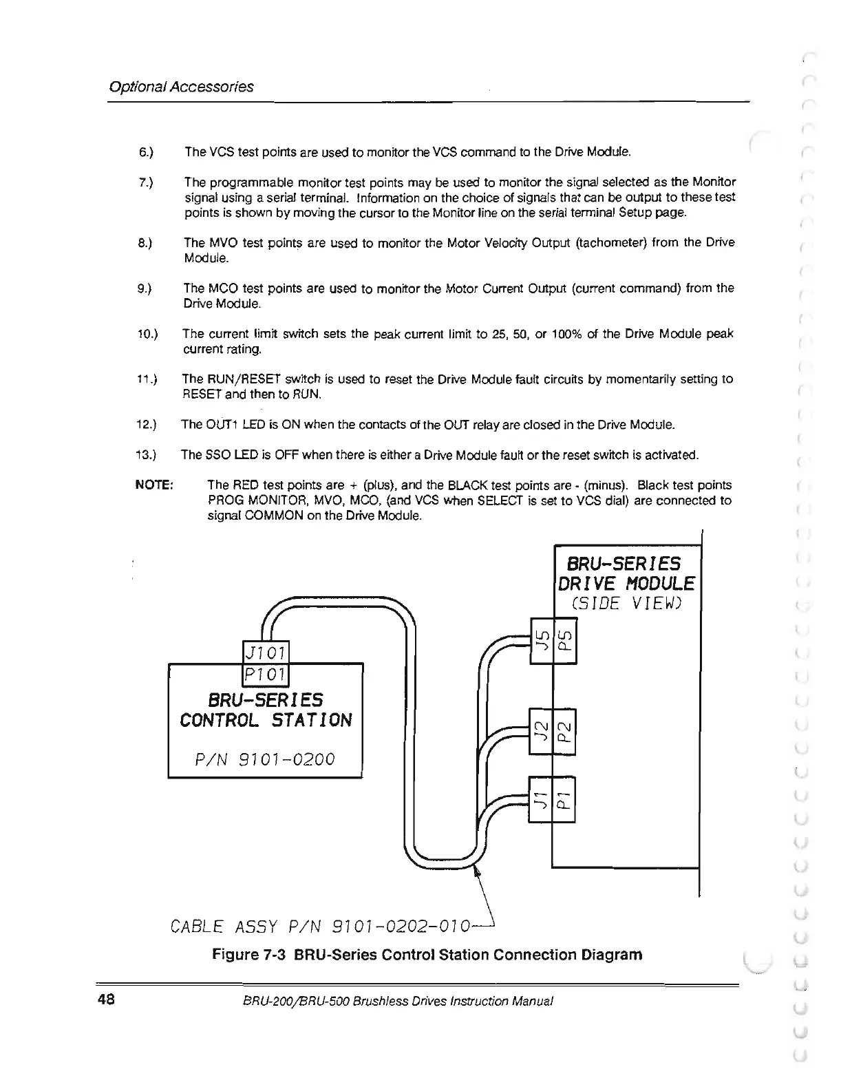
J101
P1
01
BRU-SERIES
CONTROL
STATION
PI N
910
1
-0200
C
ABLE
ASSY PI N 910 1
-0202-0
10
BRU-SERIES
DRIVE
MODULE
CSIDE
VIEW)
l.[)l.[)
')Q_
N
CL
Figure 7-3 BRU-Series Control Station Connection Diagram
BRU
-2
00I BRU-500 Brushless Drives Instruction Manual
(
(
(
(.
(.