r
(
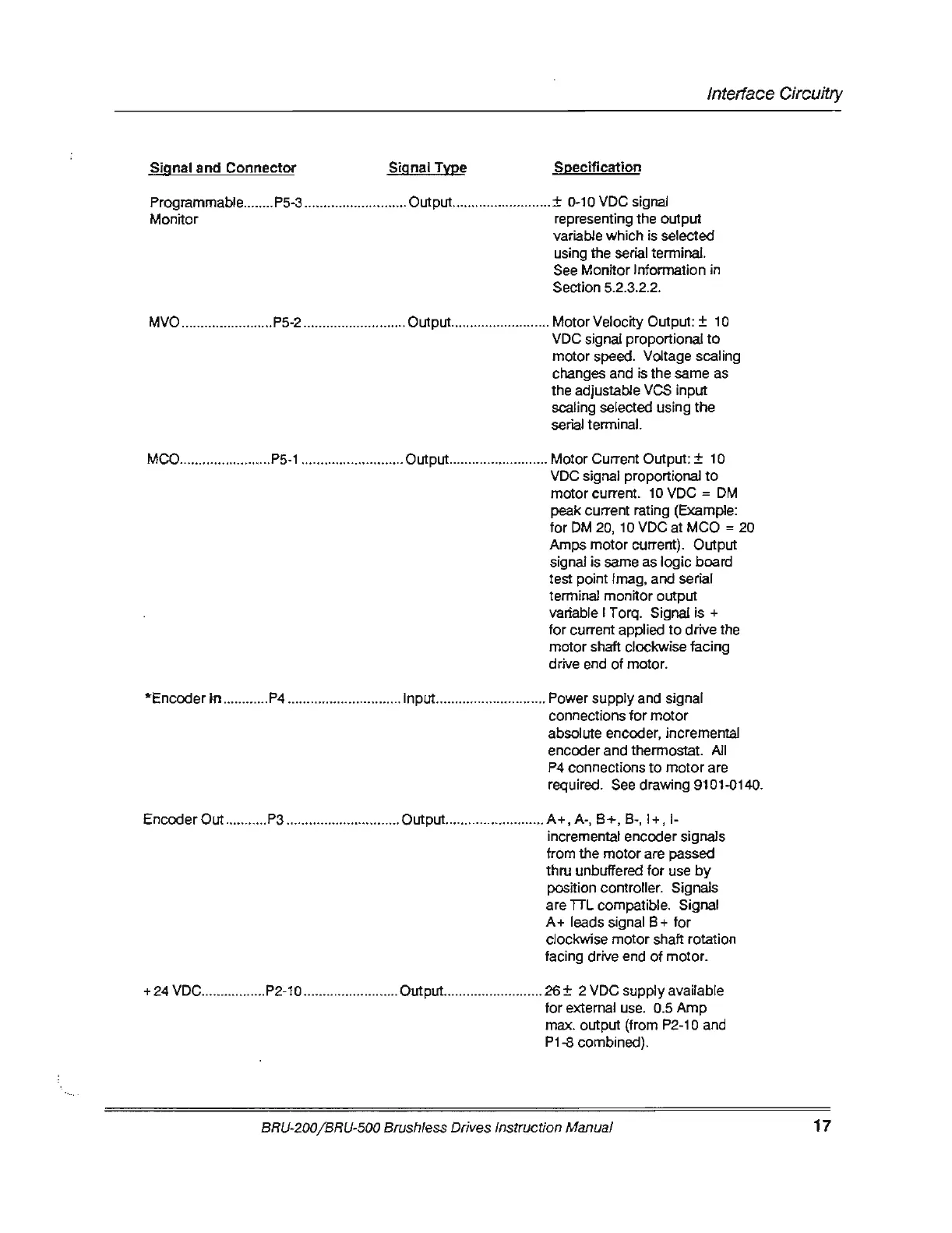
Interface Circuitry
Signal
and
Connector
Signal Type
Specification
Programmable ..
...
... P5-3
..
......
..
................. Output .........
..
..
............. ± 0-10 VDC signal
Monitor representing the output
variable which is selected
using the serial terminal.
See Monitor Information in
Section 5.2.3.2.
2.
MVO ..
..
.................... P5-2 .
...
....................... Output .......
....
..
............. Motor Velocity Output: ± 1 0
VDC signal proportional
to
motor speed. Voltage scaling
changes and is the same as
the adjustable
VCS
input
scali
ng
selected using
the
serial terminal.
MCO .....
..
.................
P5-1
..............
..
........... Output ................
..
....
..
..
Motor Current Output: ± 10
VDC
signal proportional
to
motor current.
10
VDC =
OM
peak current rating (Example:
for
OM
20, 10 VDC at MCO = 20
Amps motor current). Output
signal is same as
logic
board
test point lmag, and serial
terminal monitor output
variable I Torq. Signal
is+
for
current applied
to
drive the
motor shaft clockwise facing
drive end
of
motor.
*Enccx:Jer
In .
..
.
...
.
...
.
P4
.............................. Input ...........................
..
Power supply and signal
connections for motor
absolute
enccx:Jer,
incremental
enccx:Jer
and thermostat.
All
P4
connections
to
motor
are
required. See drawing 9101.0140.
Encoder Out ...........
P3
...................
..
.........
0utput
............
..
.........
...
A+
, A-,
8+,
8-,
1+
, !-
incremental
enccx:Jer
signals
from the motor are passed
thru unbuffered
for
use
by
position controller. Signals
are
TIL
compatible. Signal
A+
leads signal 8 +
for
clockwise motor shaft rotation
facing drive end
of
motor
.
+ 24 VDC .................
P2-1
0 ......................... Output .
..
....................... 26 ± 2 VDC supply available
for external use. 0.5 Amp
max. output (from
P2-1
0 and
P1-8 combined).
BRU-200/BRU-500 Brushless
Dri
v
es
Instruction Manual
17