Common notes
PICmicro
®
microcontrollers
This interface corresponds with Microchip application notes
TB013, TB017, TB016: How to Implement ICSP
TM
Using
PIC16CXXX OTP (PIC12C5XX OTP)(PIC16F8X Flash) MCUs.
These application notes describes requirement for target
system with In-system programming device and ISP
programmer.
Following signals are use for In-system programming of
PICmicro
®
microcontrollers.
MCLR\ / VPP reset / switch to programming mode
RB6 (GP1) clock
RB7 (GP0) data input / output
VDD power supply
GND ground
When PICmicro
®
device is programmed, pin MCLR\ / VPP is
driven to approximately 12 V. Therefore, the target system
must be isolated from this voltage provided by programmer.
RB6 and RB7 signals are used by the PICmicro
®
for In-system
programming, therefore target system mustn’t affect these
signals during In-system programming to avoid programming
errors.
Marginal verify is used after programming. Programmer must
verify the program memory contents at both minimal and
maximal power supply, therefore VDD pin of PICmicro
®
must
be isolated from rest of target system during programming.
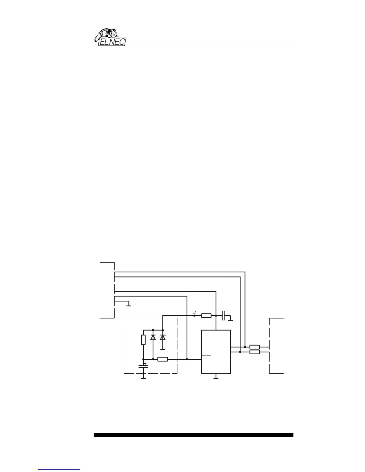
ELNEC’s recommended circuit for PICmicro:
R1 10k
R2 10k
G