16 SBC session border controllers
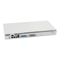
The rear panel of the device is shown in Figure 9.
Figure 9 — The rear panel of SBC-3000 (based on SMG-3016)
The table below lists rear panel connectors of the device.
Table 7 — Description of rear panel connectors of the switch
Modules with connector for power supply
Removable ventilation modules with hot-swapping
Earth bonding point of the device
2.5 LED Indication
LED indicators located on the front panel represent the current state of the device.
Device light indication in operation
2.5.1.1 SBC-1000
Light indication of the device in operation is shown in Table 8.
Table 8 — Light indication of the device operational status
non-critical device failure
no failures, non-critical warnings
 Loading...