BioProTT
TM
Flow Measurement System Version 1.00 page 16 of 75
6 Initial Set Up
6.1 Basic Considerations and Powering of Flow Meter and 4-20 mA
Circuits
Generally, devices in 4-20 mA environments can be classified based on the current source
of the 4-20 mA loop as “active” or “passive”. Passive (or 2-wire) devices rely on loop
power, whereas active (or 4-wire) devices are providing power i.e. there is a separate
power supply for the device and the loop.
The BioProTT™ flow measurement system supports both modes of operation. However,
the flow meter always needs power to operate!
In a 2 wire environment with the DC power supply located e.g. at the process control the
flow meter and the current loop are powered via PCS.
Alternatively the flow meter (always requiring a power supply!) can also provide power to
the current loop.
4-20mA
1
Sensor
31 3 1 3 1 3
Power Flow RSS
sockets with pin numbers
4
2
BioProTT flow meter
RSS +
socket -
Digital
Electronics
4
2
Flow +
socket -
PCS
-
+
+ -
+ 24V
4-20mA
-
+
+ -
Socket sample
with pin assignment
RS 232
Power supply for flow meter
Flow and RSS current loops
incl. power supply
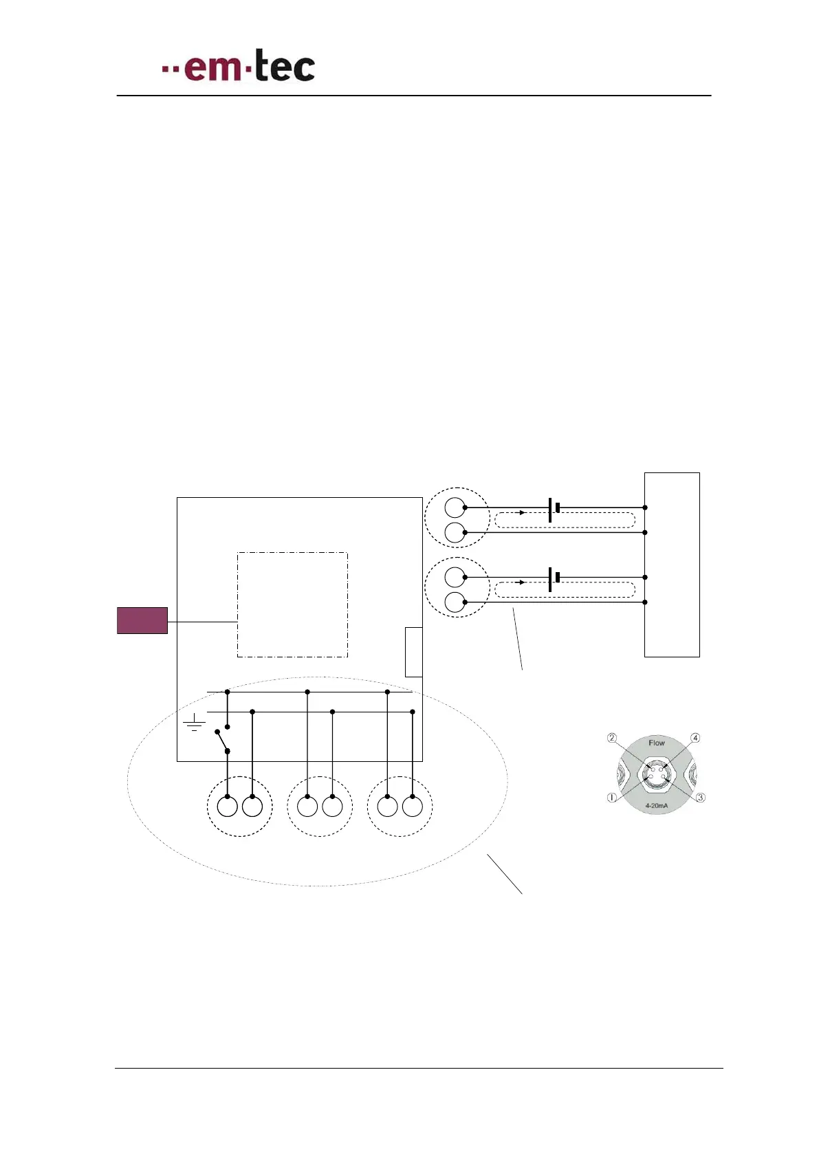
Figure 2: BioProTT flow meter schematics with focus on power supply
The figure above shows some of the electrical design which is important to properly wire
the system. The pin assignment corresponds to the pins as outlined the in following
chapters.