BioProTT
TM
Flow Measurement System Version 1.00 page 26 of 75
The PIN assignment on the terminal adapter block respectively the corresponding plug is
as follows:
For further details please see chapter INSTALLATION AND OPERATION OF
BIOPROTT™ FLOWTRACK since the features of BioProTT
TM
FlowTrack DINrail
are identical with BioProTT
TM
FlowTrack.
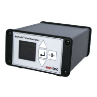
6.4 Installation and Operation of BioProTT™ FlowTrack plus
Compliance with the prescribed operating parameters and safety
information must be ensured prior to set up. The following installation
instructions must be strictly observed.
The BioProTT
TM
FlowTrack plus is designed as bench top device with sleeves that support
mounting on a flat surface.
The device is powered on or off by
pushing the switch at the rear of the flow meter when powered through the dedicated
power input
OR (alternatively) by connecting/disconnecting a DC power supply via one of the
analog interfaces (on/off switch is not active) or the power socket (which engages the
on/off switch)