BioProTT
TM
Flow Measurement System Version 1.00 page 21 of 75
6.2 Installation and Operation of BioProTT™ FlowTrack
Compliance with the prescribed operating parameters and safety
information must be ensured prior to putting into service. The following
installation instructions must be strictly observed.
The BioProTT
TM
FlowTrack can be used as bench top flow meter or mounted with screws
on surfaces.
The BioProTT
TM
FlowTrack is connected to the mains supply via the corresponding power
supply unit, via the process control or another external power supply meeting the
requirements as outlined in chapter BASIC CONSIDERATIONS AND POWERING OF
FLOW METER AND 4-20 MA CIRCUITS.
The device is being powered on or off by
pushing the switch at the rear of the flow meter when powered through the dedicated
power input
OR (alternative) by connecting/disconnecting a power supply via one of the analog
interfaces (Flow or RSS)
A green LED on the BioProTT
TM
FlowTrack indicates that it is has been powered-on. The
system requires approx. 15 s for initializing.
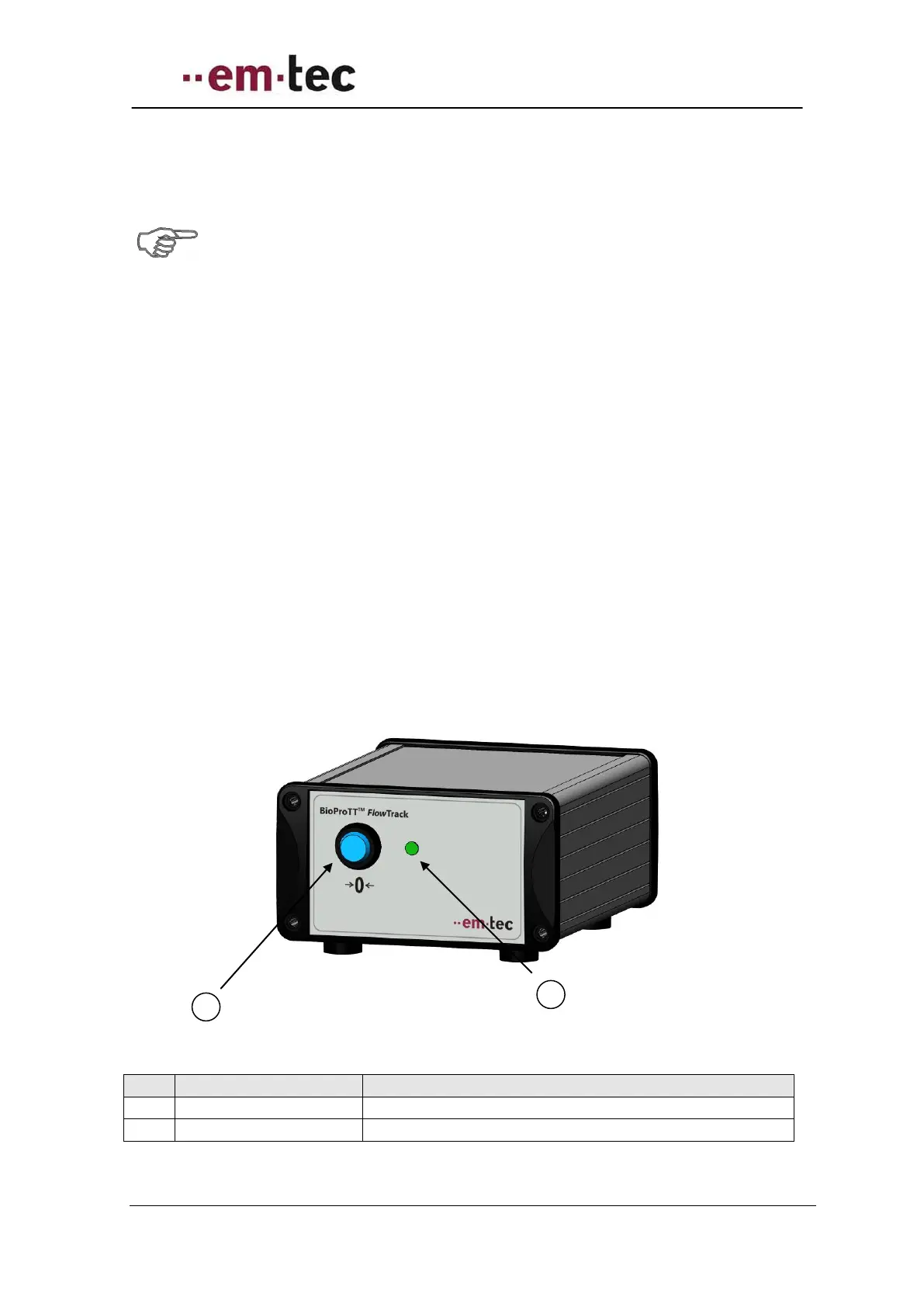
6.2.1 Front Panel BioProTT™ FlowTrack
Figure 9: Front view of BioProTT FlowTrack
Push button to adjust offset at zero flow
A green light indicates a functioning device