BioProTT
TM
Flow Measurement System Version 1.00 page 3 of 75
TABLE OF CONTENTS
1 INTENDED USE .................................................................................................................................... 6
2 GENERAL SAFETY AND IMPORTANT INFORMATION ........................................................... 6
2.1 GENERAL SAFETY INFORMATION .................................................................................................... 6
2.2 GENERAL IMPORTANT INFORMATION ............................................................................................. 8
3 SYMBOLS, UNITS AND ABBREVIATIONS .................................................................................... 9
3.1 SYMBOLS USED IN THESE OPERATING INSTRUCTIONS ..................................................................... 9
3.2 SYMBOLS ON EXTERNAL POWER SUPPLY UNIT............................................................................... 9
3.3 SYMBOLS ON FLOW METER, SENSORS AND ON PACKAGING ......................................................... 10
3.4 UNITS ............................................................................................................................................ 12
3.5 DEFINITIONS AND ABBREVIATIONS ............................................................................................... 12
4 DESCRIPTION OF MEASURING PRINCIPLE ............................................................................. 13
5 PACKAGING CONTENTS ................................................................................................................ 14
6 INITIAL SET UP ................................................................................................................................. 16
6.1 BASIC CONSIDERATIONS AND POWERING OF FLOW METER AND 4-20 MA CIRCUITS .................... 16
6.1.1 Wiring in “Active” Set-Up when Flow Meter is Not Relying on Current Loop Power ........... 18
6.1.2 Wiring in “Passive” Set-Up when Powering Flow Meter via Current Loop .......................... 20
6.2 INSTALLATION AND OPERATION OF BIOPROTT™ FLOWTRACK ................................................... 21
6.2.1 Front Panel BioProTT™ FlowTrack ...................................................................................... 21
6.2.2 Rear Panel BioProTT™ FlowTrack ........................................................................................ 22
6.2.2.1 Pin Assignment and Cable Colors for Round Connector for Digital Interface .............................. 23
6.2.2.2 Pin Assignment and Cable Colors for Round Connector for Power Analogue Flow and RSS
Interfaces 23
6.2.3 Connecting and powering up the system ................................................................................. 24
6.3 INSTALLATION AND OPERATION OF BIOPROTT™ FLOWTRACK DINRAIL NOTE: PRELIMINARY
INFORMATION! ............................................................................................................................................ 25
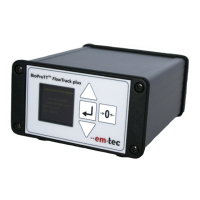
6.4 INSTALLATION AND OPERATION OF BIOPROTT™ FLOWTRACK PLUS .......................................... 26
6.4.1 Front Panel BioProTT™ FlowTrack plus ............................................................................... 27
6.4.2 Menu Structure of BioProTT™ FlowTrack plus ..................................................................... 28
6.4.3 Rear Panel BioProTT™ FlowTrack plus ................................................................................ 29
6.4.4 Connecting and Powering up .................................................................................................. 29
6.5 MOUNTING .................................................................................................................................... 30
7 PERFORMING MEASUREMENTS ON TUBING SYSTEMS USING BIOPROTT
TM
CLAMP-
ON TRANSDUCERS .................................................................................................................................... 31
7.1 INSTALLATION OF THE BIOPROTTTM CLAMP-ON TRANSDUCER ................................................. 31
7.2 CLAMPING ONTO TUBE ................................................................................................................. 31
7.3 MEASUREMENT ACCURACY AND TUBE ARRANGEMENT ............................................................... 32
7.4 RECEIVED SIGNAL STRENGTH (RSS / ACOUSTIC COUPLING) ........................................................ 33
7.5 USE OF ACOUSTIC COUPLANT ....................................................................................................... 33
7.6 ZERO ADJUSTMENT ....................................................................................................................... 35
7.7 PERFORMING FLOW MEASUREMENTS ........................................................................................... 35
7.7.1 Measurement Using the Analog Interface of BioProTT™ FlowTrack, BioProTT™ FlowTrack
plus and BioProTT™ FlowTrack DINrail ............................................................................................. 35
7.7.1.1 Received Signal Strength (RSS / Acoustic Coupling) ................................................................... 35
7.7.1.2 Flow Value .................................................................................................................................... 36
7.7.2 Measurement Using the Digital Interface (RS232) of the Different BioProTT™ Flow Meters
38
7.7.3 Measurements Using BioProTT™ FlowTrack plus ................................................................. 41
7.7.3.1 Flow Value and Coupling ............................................................................................................. 41