BioProTT
TM
Flow Measurement System Version 1.00 page 29 of 75
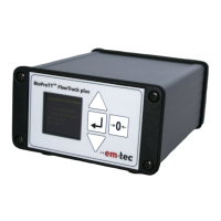
6.4.3 Rear Panel BioProTT™ FlowTrack plus
The rear panel of BioProTT™ FlowTrack plus is identical to the flow meter without
display, i.e. BioProTT™ FlowTrack. Please see chapter REAR PANEL BIOPROTT™
FLOWTRACK.
6.4.4 Connecting and Powering up
The flow meter is operated with the provided power supply.
Please note: the flow meter can alternatively be powered via an external power supply
either via the dedicated power input or either of the analog sockets. For details see chapter
BASIC CONSIDERATIONS AND POWERING OF FLOW METER AND 4-20 MA
CIRCUITS.
1. Connect power supply unit that is shipped with the device
2. Connect Clamp-On Transducer to the BioProTT
TM
flow meter.
3. Connect the 4-20 mA and/or digital serial output to your data acquisition system.
The connectors should be firmly tightened. Unused connector sockets should be
covered with provided flexible grip caps.
4. Power on the device with the switch. Approx. 15s are needed for a complete
initialization, which is done when the flow sreen appears. The system will
automatically start to transfer measurement values.
Please note: The Current loops can either be powered through the process control
system or are powered by the flow meter. The wiring needs to be done as shown in
chapter INITIAL SET UP.
5. Clamp transducer around tubing (for details see chapter INSTALLATION OF THE
BIOPROTTTM CLAMP-ON TRANSDUCER). An arrow on the sensor lid
indicates the flow direction; make sure that sensor is oriented in the flow
direction otherwise negative readings occur. Negative Values will be shown
correctly on the display and in the digital reading. However, the analog interface
does only have a limited interval for showing. Make sure the tubing size and
material fit and the sensor lid is closed (locked in).
6. If not yet done fill tubing with liquid. You will see an increase of the RSS value on
the screen (or the other corresponding interfaces).
7. Make sure that the liquid is not in motion and press the (zero) Offset adjust button
on BioProTT™ FlowTrack plus when in the flow screen.
8. The flow measurement system is now ready for use.