BioProTT
TM
Flow Measurement System Version 1.00 page 55 of 75
8.4.3 Method 3 – Checking Functionality with a Voltmeter
It is also possible to test the functionality of the current loops (Flow or RSS) with a
voltmeter. In this case, a resistor has to be applied. Ohm’s law has to be observed to
calculate the correct current through the resistor. The loop can be powered either externally
or via flow meter as shown in the diagram below.
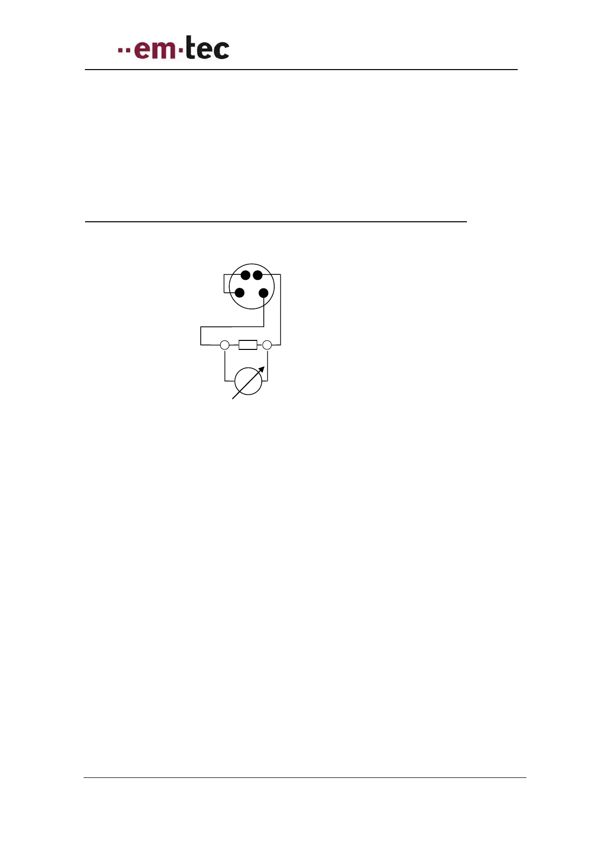
Schematics - looking at pins of rear of flow meter of either Flow or RSS socket
Figure 19: Schematics - looking at pins of rear of flow meter of either Flow or RSS socket
Tolerances for voltage measurement (range of voltmeter 0 – 15 V) are as follows:
Resistor min 100 Ohm, max. 600 Ohm
Tolerance of resistor min 1% better 0,1%
Internal impedance of voltmeter minimal 1 MOhm