BioProTT
TM
Flow Measurement System Version 1.00 page 54 of 75
8.4.2 Method 2 – Providing Power Externally in Current Loop and
Measuring with Ampermeter
Wire colour
(in supplied cabling)
Connect pin 2 to “+” of battery /
24V DC power source
Connect pin 3 to the appropriate
connector of your reading device
/ data logger, e.g. “return” or “-“
of an ampermeter. Close loop by
connecting also to “-“ of battery
Connect pin 4 to appropriate
connector of your reading device
ampermeter e.g. “send” or “+”
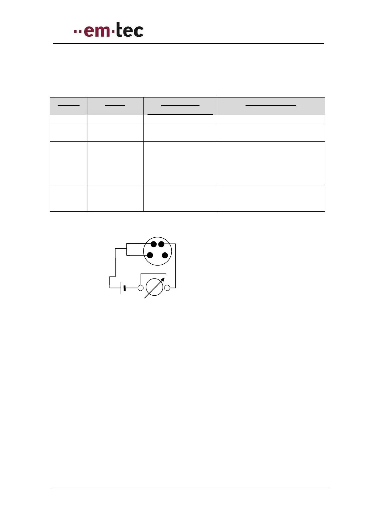
Figure 18: Schematics - looking at pins of rear of flow meter of either Flow or RSS socket
Tolerances for current measurement (range of ampermeter 4-20 mA) are as follows:
Max 1% + 5 digits at > 50.000 mA range
Internal resistance < 10 Ohm
Return (-) Send(+)
of ampermeter