BioProTT
TM
Flow Measurement System Version 1.00 page 25 of 75
6.3 Installation and Operation of BioProTT™ FlowTrack DINrail
Note: Preliminary Information!
Compliance with the prescribed operating parameters and safety
information must be ensured prior to putting into service. The following
installation instructions must be strictly observed.
The BioProTT
TM
FlowTrack DINrail flow meter supports DIN Rail mounting, e.g. for use
in cabinets of process controls. From a feature point of view, the device is identical with
the BioProTT
TM
FlowTrack. The physical connections have been moved and the form
factor has partially been changed to support specific installation environment.
BioProTT
TM
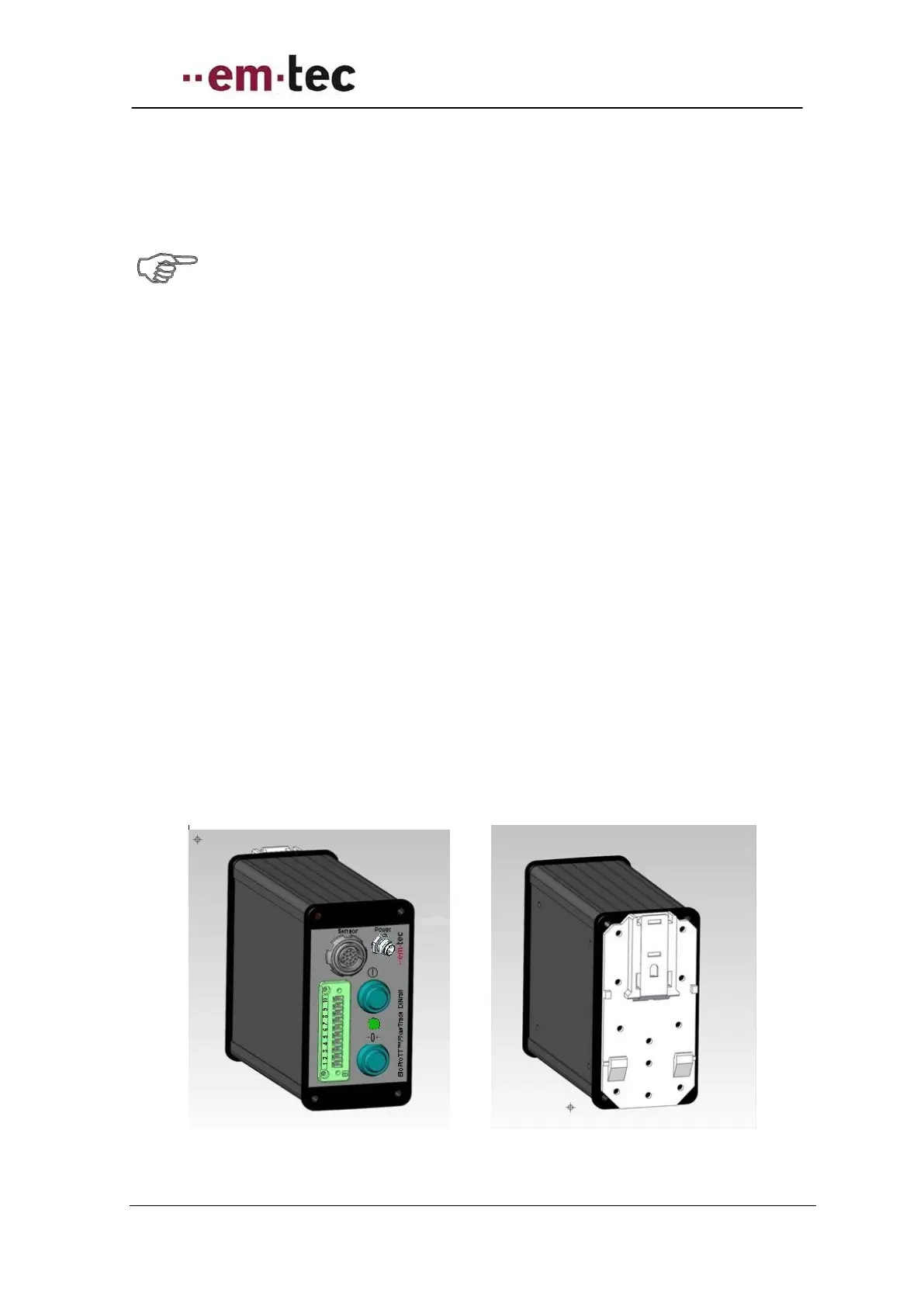
FlowTrack DINrail is clamped onto the DIN rail by flipping the handle on the
adapter of the back of the device. Please ensure that it is firmly mounted onto the rail
before setting up any connections.
BioProTT
TM
FlowTrack DINrail is connected to the mains via the process control or
another external power supply meeting the requirements as outlined in chapter BASIC
CONSIDERATIONS AND POWERING OF FLOW METER AND 4-20 MA CIRCUITS.
The device is powered on or off by
Pushing the switch at the rear of the flow meter when powered through the dedicated
power input.
Please note: this switch is available, but usually not used, i.e. typically the switch is
always in the “on” position. Power on or off is handled via process control.
Switching power on or via process control
A green LED on the BioProTT
TM
FlowTrack indicates that it is ready to use after it has
been powered-on:
Figure 11: Front and rear view of BioProTT FlowTrack DINrail