BioProTT
TM
Flow Measurement System Version 1.00 page 22 of 75
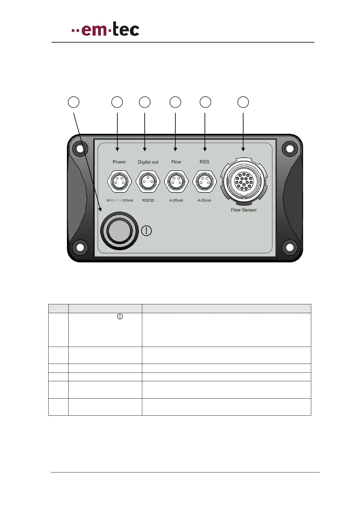
6.2.2 Rear Panel BioProTT™ FlowTrack
Figure 10: Rear view of BioProTT FlowTrack
Push the button to power the device on or off.
Note: this button is only relevant when power is
supplied via the power socket. The button does not
affect power supplied via either Flow or RSS socket.
4-pin connecting socket for DC power.
Note: only 2 pins are actually used.
3-pin connecting socket for the signal digital interface.
4-pin connecting socket for the analogue flow signal.
4-pin connecting socket for the analogue signal
“received signal strength” (RSS).
14-pin connecting socket for the
BioProTT™ Clamp-On Transducer.