BioProTT
TM
Flow Measurement System Version 1.00 page 19 of 75
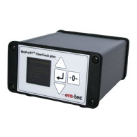
For details see the circuit diagram below and observe the wiring instructions.
Figure 5: BioProTT flow meter rear view with one analogue plug connected -example w/ flow socket
Wire color
(in supplied cabling)
Ground (GND) /
Return of PCS
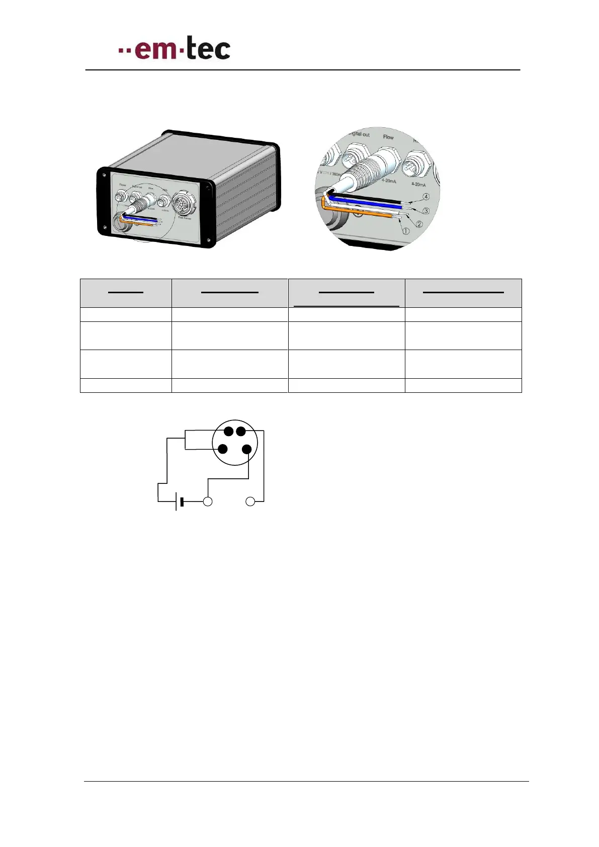
Figure 6: Schematics - looking at pins of rear of flow meter of either Flow or RSS socket
Please note: the basic wiring diagram is identical to the “active” set-up, just the
power source is different.
Return (-) Send(+)
of PCS