EM TEST Compact NX5
Operating Manual V 1.06 116 / 143
Test routines termination
The test routine for power fail starts with an event with the duration (td), followed by a repetition time (tr). For
operating, the compact NX generator has the following handling for the test routine
Test routine in a testlink implemented
Operating
The power fail simulator operates in the following mode:
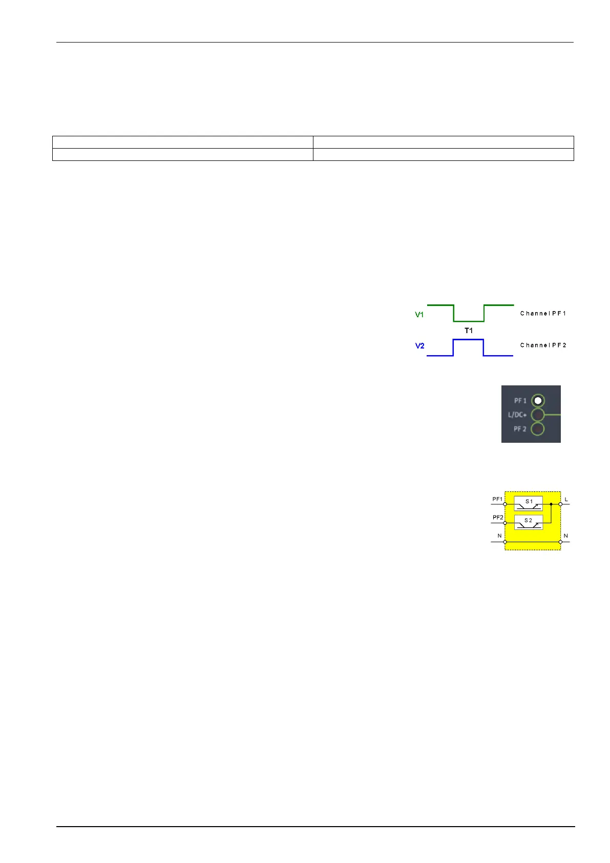
PF1: The voltage supply at channel PF1 will be interrupted for the preselected time T1.
PF2: The voltage supply at channel PF2 will be interrupted for the preselected time T1.
U: Channels PF1 and PF2 are supplied with different voltages; e.g.
channel PF1 with nominal voltage, channel PF2 with 15% under-
voltage.
- channel PF1 is switched off for the preselected time T1.
- channel PF2 is switched on for T1.
LED
Two LED’s mounted on the front panel show if a channels is active or not. The LED of an
active channel is lighted. During mode U the LED display switches from one channel to the
other.
Voltage interference
In order to accelerate the test procedure the voltage interference may be generated
repetitively. In the operating mode „AUTO“, the events are released at a preselected interval
time.
Power switches
The power unit of the simulator consists of two electronic power switches S1 and S2. The two
separated input channels PF1 and PF2 are connected to each other at the front panel of the
simulator via S1 and S2.
Input channels
The input channels PF1 and PF2 are located at the rear part of the equipment. Attention has to be given to the
following:
1. The phase shall be connected correctly. When putting into operation check the lines with a phase
tester or with the incorporated LED phase.
2. Phase must be set on L, neutral must be set on N.
3. This applies to both channels. If during installation phase and neutral is changed, the operator will
cause a short-circuit at the input plug of the channel.
4. The neutral of both channels is connected internally and directly leads to the output.
5. The power switches can bear no more than a voltage of 350Veff.
6. If isolating transformers are used special care shall be taken to have both channels in phase.
Otherwise too high voltages, in difference mode, may occur and destroy the internal protection
devices (varistors).
 Loading...