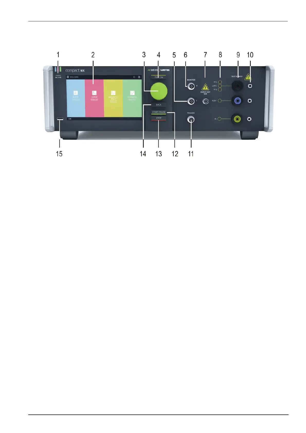
1 ACTIVE
Indicates that this unit is active
2 Touch screen and user interface
With the 7” capacitive touch screen display the user controls the equipment. The display indicates the status of
the generator and test equipment.
3 Wheel (Inc. / Dec / Enter)
Rotate for increments or decrements a selected parameter. Push change the digit and hold with a numeric
value or selects from a list of parameters. Press to change adjustment range. Selected range will be shown
briefly next to selected parameter. Push and hold to “zero” to nearest range.
4 Test On
By pressing the key "Test On" follows the functions:
- Activate the high voltage power unit; HV is ready to start.
- Switches ON the supply to the EUT test supply (only with built in Power Fail module).
5 CRO I (surge)
At the BNC output the current pulse (surge) of the generator can be measured galvanic separated.
- Impedance measuring instrument: >1MΩ.
- Max. output voltage: 10V 10% at 2.5 kA output current.
6 CRO V (surge)
At the BNC output the voltage pulse (surge) of the generator can be measured galvanic separated.
- Impedance measuring instrument: >1MΩ.
- Max. output voltage: 10V 10% at 5 kV impulse voltage.
7 HV pulse burst output 50
External coupling devices such as the capacitive coupling clamp and the 3-phase coupling networks are
connected to the coaxial 50 ohm output. Also the calibration of the generator is handled at this output.
Note: The burst signal is present on this output at every coupling mode.
8 Coupling mode
The LED indicates
- actual coupling mode of the Burst or Surge impulse to lines L, N, PE, or + for dc
- active power supply source PF1, PF2
 Loading...