EasyManuals Logo

Em-Trak A100 User Manual

Em-Trak A100
84 pages
To Next Page IconTo Next Page
To Previous Page IconTo Previous Page
Page #33 background imageLoading...
Page #33 background image
Installation
Page 31
4 Installation
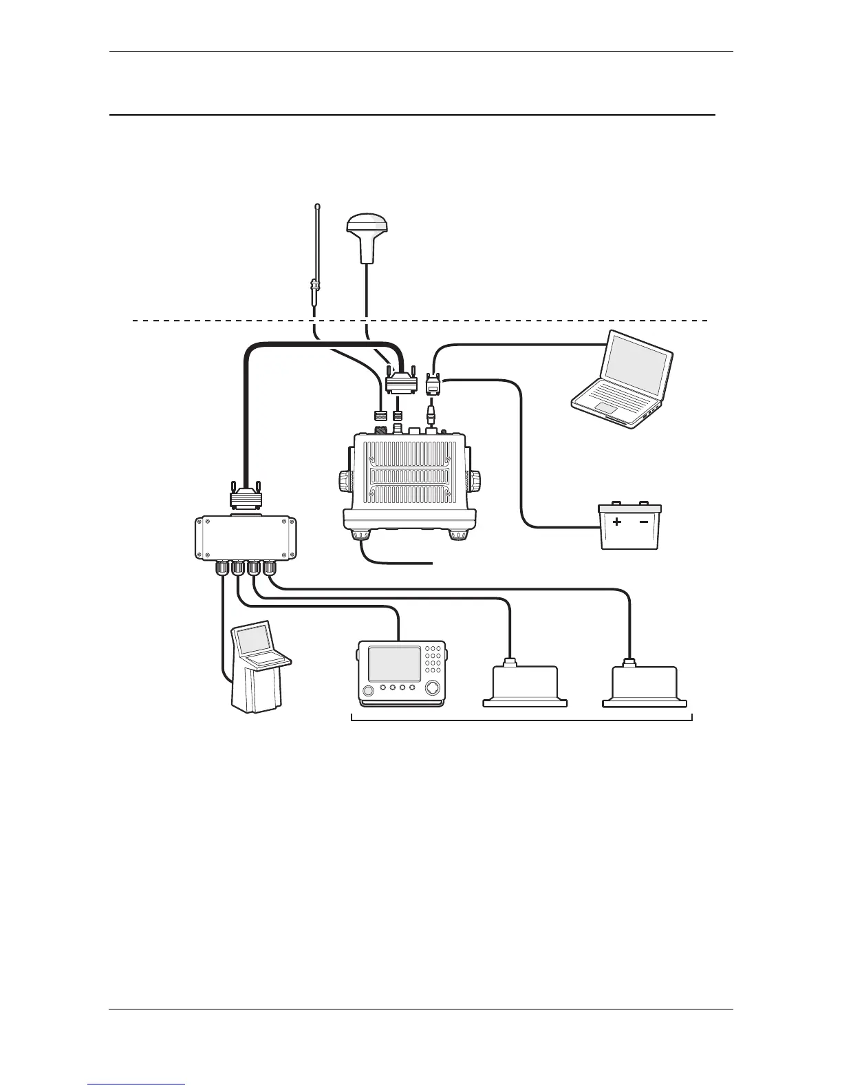
The transceiver has been designed for ease of installation. The transceiver is a ‘one box’ design containing
both the transceiver and display. An external junction box is provided to simplify connection of sensor and
display data wiring. A typical system and connection diagram is provided in
Figure 32.
Figure 32 Typical AIS transceiver connection
The main elements of installation are:
1. Mount the transceiver and junction box in a suitable location.
2. Install VHF antenna according to manufacturers instructions.
3. Install the GNSS antenna.
4. Connect data interfaces.
5. Apply power and configure the transceiver.
6. Confirm correct operation.
7. Complete the installation log.
GNSS antenna
12/24V DC Supply
Pilot equipment
Optional PC
VHF antenna
Above decks
Below decks
Junction box
Displays
(ECDIS, RADAR)
Ships sensor data
(DGPS, GYRO, Heading)

Table of Contents

Other manuals for Em-Trak A100

Questions and Answers:

Question and Answer IconNeed help?

Do you have a question about the Em-Trak A100 and is the answer not in the manual?

Em-Trak A100 Specifications

General IconGeneral
BrandEm-Trak
ModelA100
CategoryTransceiver
LanguageEnglish

Related product manuals