Installation
Page 43
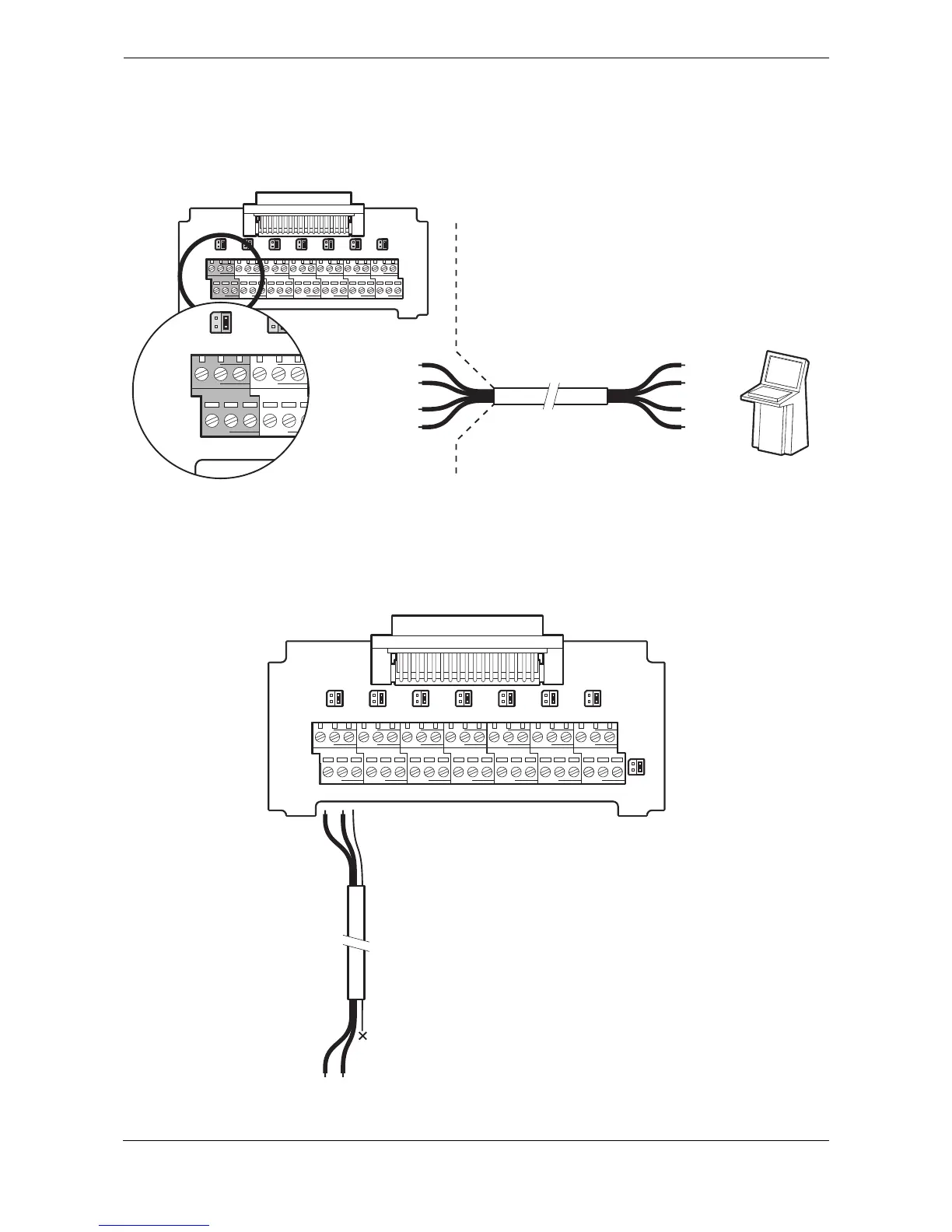
An example of connection to external display equipment is provided in Figure 45, and connections to other
equipment and sensors follow the same scheme. To determine the ‘A’ and ‘B’ signal lines on external
equipment use a digital volt meter to measure the signal line voltage referenced to ground. If the voltmeter
shows a negative voltage the ‘A’ signal line is being measured, a positive voltage indicates the ‘B’ signal line.
Figure 45 Example connection to external display equipment
Shielded cable should be used for data interface connections and the shield should be connected to the ground
at the 'talker' end of the connection. If the transceiver is being connected to a display system then the cable
shield should be connected to ground at the transceiver junction box as shown in
Figure 46.
Figure 46 Connecting data interface cable shields