Installation
Page 44
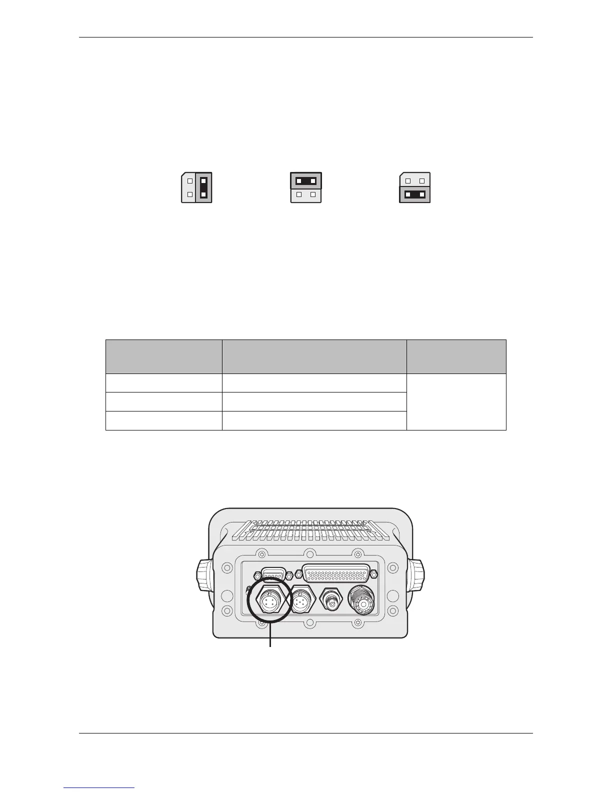
The junction box provides jumpers to select alternative line termination configurations for data input
connections from remote equipment. The line termination options are:
● None - no line termination, suitable for short cable runs less than 10m (as supplied).
● R - 120 Ohm line termination, suitable for longer cable runs greater than 10m.
● RC - AC 120 Ohm / 1uF termination. Not used.
Select the appropriate line termination option for each data input connection using the jumper adjacent to the data
input connection in the junction box. The jumper positions for each termination option are shown in
Figure 47.
Figure 47 Line termination options
Along with data port connections the junction box also provides connections to the AIS transceiver alarm relay
contacts. The common and normally open alarm contacts are duplicates of the alarm relay connections
available at the power connector (see
Table 5) whilst the normally closed contact is only provided at the junction
box. The alarm relay connections are described in Table 5. Use the alarm connections appropriate to the
vessels alarm system.
Table 5 Alarm relay connections
4.4.5 Power and alarm connections
Power is connected to the transceiver via the supplied four way power and alarm cable as shown in Figure 48.
Figure 48 Power connection
Junction box alarm
connection
Function Contact rating
COM Alarm relay common connection
220V or 2A or 60W
maximum
NC Alarm relay normally closed connection
NO Alarm relay normally open connection