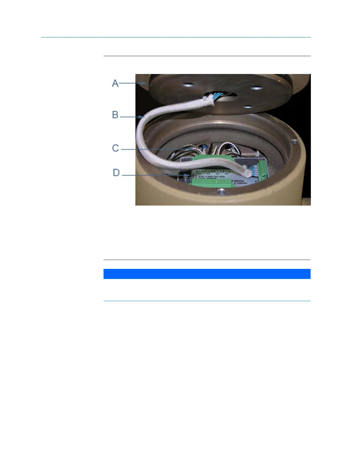
Acquisition Module cable and transducer wiringFigure 3-27:
A. Base Enclosure gasket
B. Acquisition cable
C. Acquisition wiring terminal blocks
D. Acquisition Module
NOTICE
Ensure that the transducers identified as belonging to end 1 are installed on end 1 (A1,
B1, C1 or D1) of the meter holder and those identified as belonging to end 2 (A2, B2, C2
or D2) are installed on end 2 of the meter housing.
6. Remove the three Acquisition Module flat head screws and split lock washers, then
remove the Acquisition Module from the Base Enclosure.
7. Insert the new Acquisition Module into the Base Enclosure and secure with the three
split lock washers and flat head screws.
8. Reattach the terminal blocks onto the Acquisition Module (3 mm flat head screw
driver required) for the corresponding chord (3414 four path meters A1, A2, B1, B2
C1, C2, D1, and D2; 3412 two path meters A1, A2, B1, B2; or 3411 single path
meters A1 and A2). Make sure the transducer wires have good contact with the
terminal block and the terminal block screws are tight.
9. When you have completed attaching the Transducer wire terminal blocks and the
Acquisition cable terminal block to the Acquisition Module, check the Base
Enclosure o-ring and reinstall if necessary.
Meter repairs
84 Gas Ultrasonic Flow Meters

 Loading...


