Emerson FB1200 Flow Computer Instruction Manual
D301782X012
March 2019
I/O Configuration and Wiring 69
Note
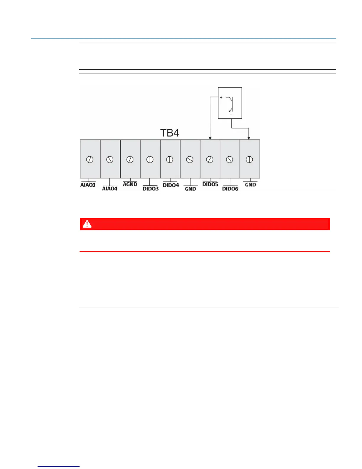
Figure 3-20 shows pulse input wiring for PIDIDO5. PIDIDO5 and PIDIDO6 share the same GND
terminal. PIDIDO3 and PIDIDO4 share a different GND terminal.
Figure 3-20: PI Wiring (with Optional I/O Module)
3.6 Connecting the RTD
EXPLOSION HAZARD: Ensure the area in which you perform this operation is non-hazardous.
Performing this operation in a hazardous area could result in an explosion.
RTD connections reside on the terminal plate under the rear end cap. The flow computer supports 2-
wire, 3-wire, and 4-wire operation. Route the RTD cable through the conduit fittings and connect
them on the terminal plate (as shown on Figure 3-21 and Figure 3-22).
Note
The device defaults to the 4-wire RTD configuration; you can change this setting in FBxConnect.