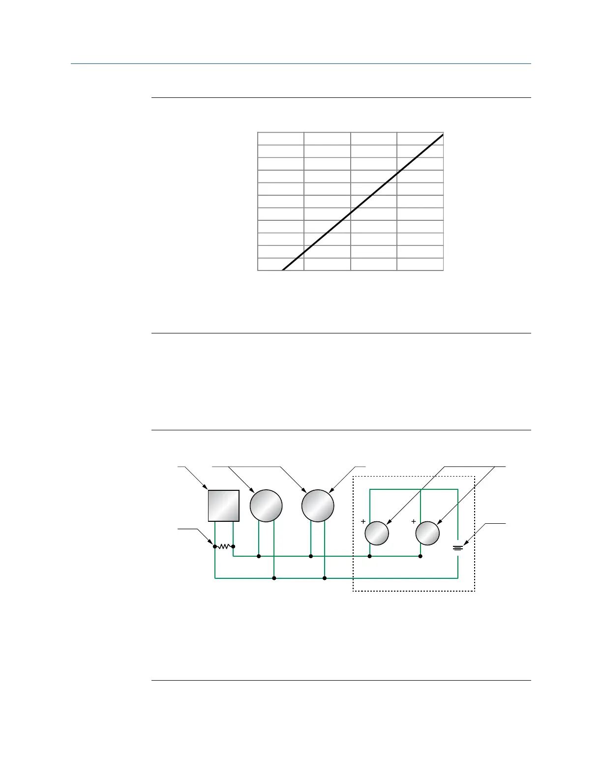
Figure 4-8: Externally-powered mA/HART output: maximum loop resistance
0
100
200
300
400
500
600
700
800
900
1000
1100
0 7.5 15.0 22.5 30.0
B
A
A. Maximum resistance (Ω)
B. External supply voltage (V)
4.4.3
Wire the mA/HART
®
multidrop installation (internally or
externally powered)
Procedure
See the Figure 4-9 for information on wiring a mA/HART multidrop installation.
Figure 4-9: mA/HART multidrop wiring
A. 250–600 Ω resistance
B. HART-compatible host or controller
C. HART-compatible transmitter (internally powered)
D. Micro Motion 5700 transmitter (internally powered) mA/HART connections
E. SMART FAMILY
™
transmitters
F. 24 VDC loop power supply required for external transmitter
Wiring the channels Installation Manual
April 2022 MMI-20027478
30 Micro Motion 5700 Transmitters with Configurable Inputs and Outputs