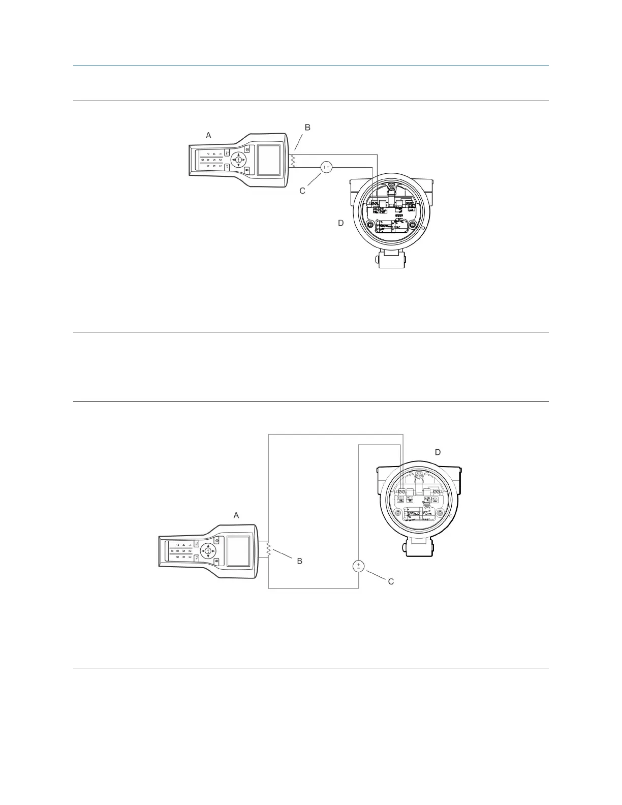
Figure D-1: Field communicator connection to transmitter terminals
A. Field communicator
B. 250–600 Ω resistance
C. External power supply
D. Transmitter with end-cap removed
2. To connect to a point in the local HART loop, attach the leads from your field communicator to any
point in the loop and add resistance as necessary.
Your field communicator must be connected across a resistance of 250–600 Ω.
Figure D-2: Field communicator connection to local HART loop
A. Field communicator
B. 250–600 Ω resistance
C. External power supply
D. Transmitter with end-cap removed
3. To connect to a point in the HART multidrop network, attach the leads from your field communicator
to any point on the network.
Configuration and Use Manual Using the field communicator with the transmitter
MMI-20020954 March 2021
Configuration and Use Manual 181