PACSystems Ethernet Switch SLM042 User Manual Section 3
GFK-3123A Jan 2020
Hardware Overview 5
3.2 SLM042 Series
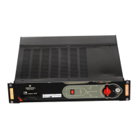
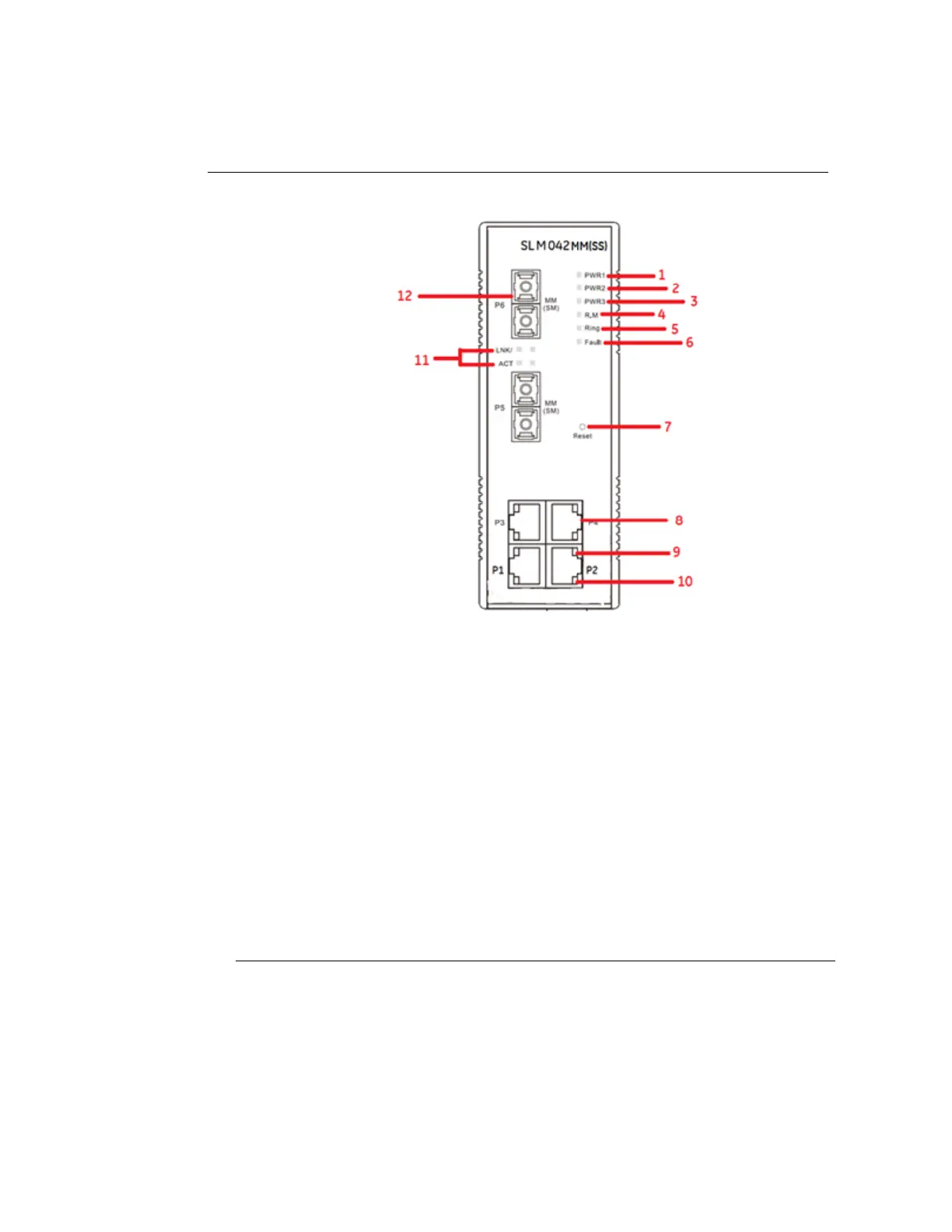
Figure 3: Anatomy
1. LED for PWR1. When the PWR1 links, the green led will be light on.
2. LED for PWR2. When the PWR2 links, the green led will be light on.
3. LED for PWR3. When the PWR3 links, the green led will be light on.
4. LED for R.M (Ring master). When the LED light on, it means that the switch is the
ring master of Ring.
5. LED for Ring. When the LED light on, it means the Ring is activated.
6. LED for Fault Relay. When the fault occurs, the amber LED will be light on.
7. Reset button. Push the button 3 seconds for reset; 5 seconds for factory default
8. LED for Ethernet ACT status
9. LED for Ethernet LINK status
10. LED for Fiber ACT/LINK status
11. 100Base-FX Fiber ports.