CH2 input. A closed switch drives a TRUE output. An Open switch drives a
FALSE output.
Note
Any dry contact input may optionally be inverted by the device, to change
the discrete logic state. This is useful, for instance, if a normally open switch
is used to replace a normally closed switch.
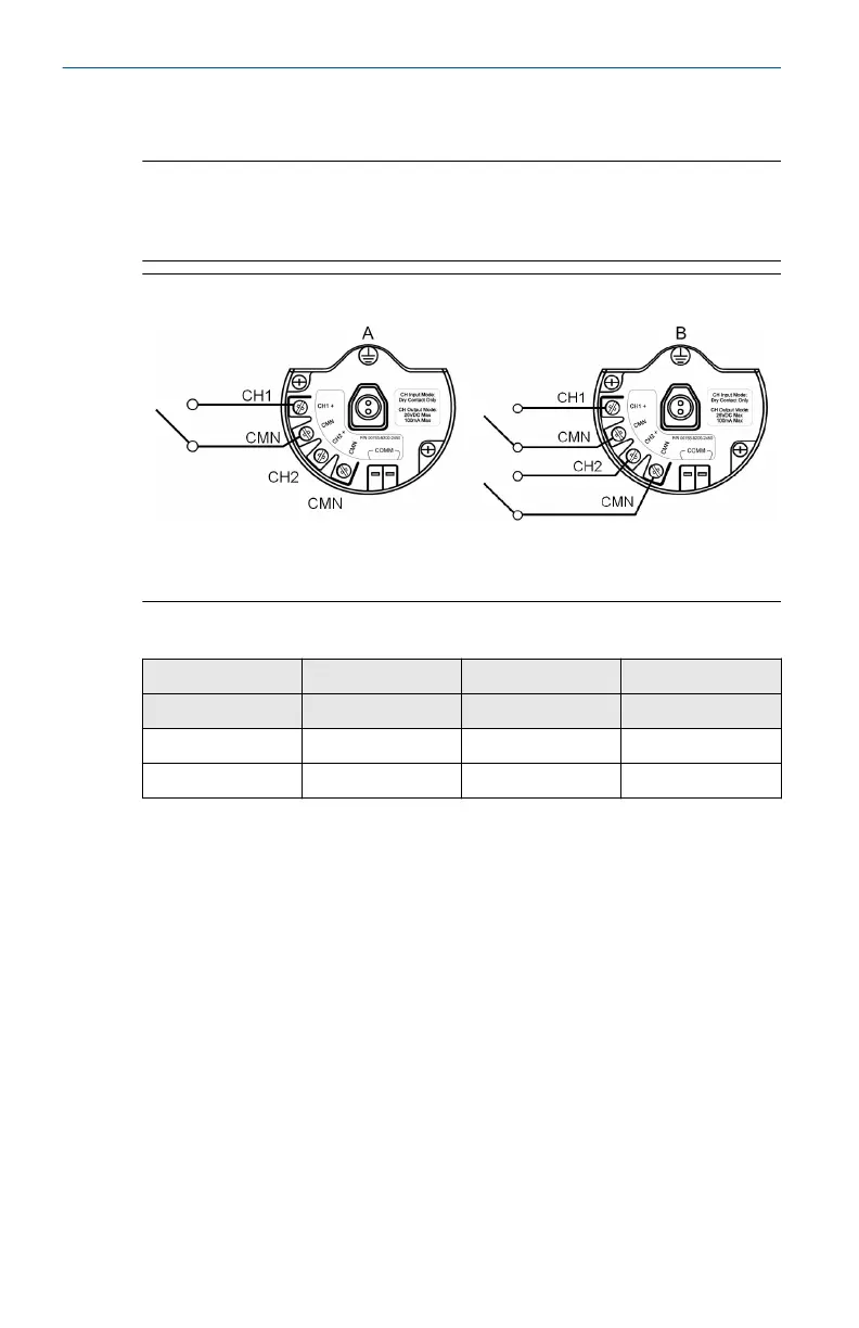
Figure 6-2: Single and Dual Input
A. Single Input
B. Dual Input
Table 6-1: Single or Dual Input
Switch input Wireless output Switch input Wireless output
CH1 PV CH2 SV
Closed TRUE (1.0) Closed TRUE (1.0)
Open FALSE (0.0) Open FALSE (0.0)
6.2.2 Dual input, limit contact logic
When configured for Limit Contact Logic, the Rosemount 702 Transmitter
will accept the input from two single pole single throw switch on inputs CH1
and CH2, and will use limit contact logic for the determination of the
wireless outputs.
Quick Start Guide April 2021
20 Emerson.com/Rosemount