Figure 6-16: Plunger Arrival Terminal Diagram
The wiring connections to the ETC Cyclops Sensor are made according to
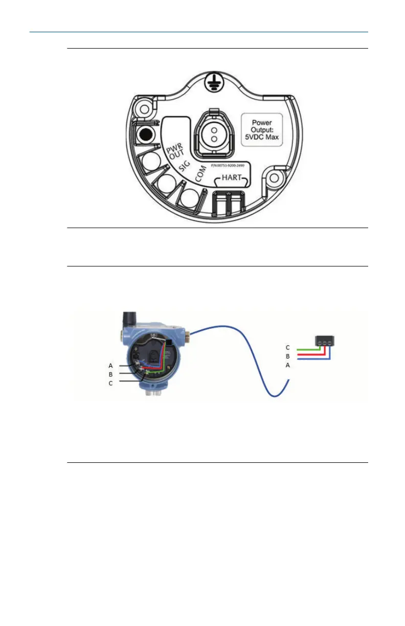
Figure 6-17.
Figure 6-17: Wiring Configuration
Plunger arrival sensor ETC Cyclops Sensor
A. PWR
B. SIG
C. COM
For mounting and maintenance of the ETC Cyclops Sensor, refer to the ETC
Cyclops Plunger Arrival Sensor Manual.
6.8.2 System Verification
After installation of the 702DX52 for plunger arrival one must verify
functionality.
Quick Start Guide April 2021
32 Emerson.com/Rosemount