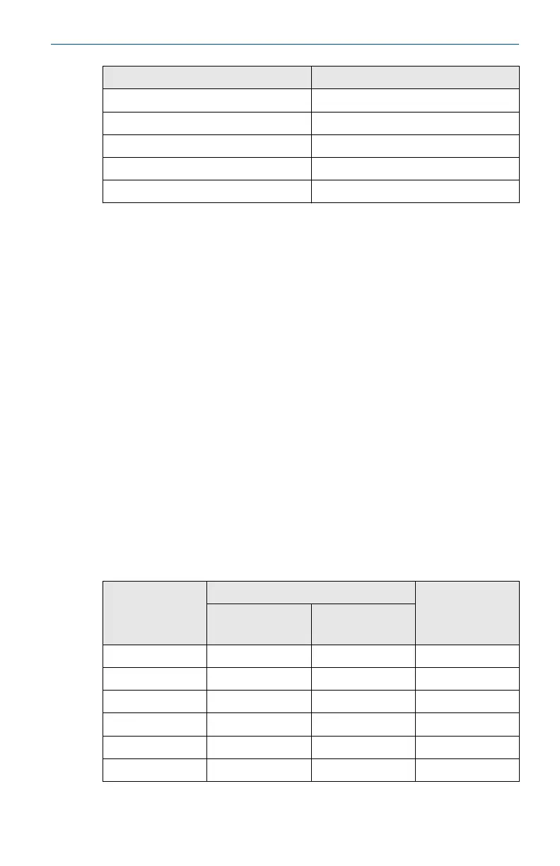
Sensor terminal parameters (input) Switch terminal parameters (output)
U
O
= 6.6 V U
i
= 26 V
I
O
= 13.4 mA I
i
= 100 mA
P
O
= 21.8 mW P
i
= 0.65 W
C
O
= 10.9 µF N/A
L
O
= 25 µH N/A
Special Conditions for Safe Use (X):
1. The surface resistivity of the antenna is greater than 1 GΩ. To avoid
electrostatic charge build-up, it must not be rubbed or cleaned with
solvents or dry cloth.
2. The Model 701PBKKF Power Module, MHM-89004 Blue Power
Module or Intelligent Power Module 71008 may be replaced in a
hazardous area. The Power Modules have a surface resistivity greater
than 1 GΩ and must be properly installed in the wireless device
enclosure. Care must be taken during transportation to and from the
point of installation to prevent electrostatic charge build-up.
8.10 China
8.10.1 I3 China Intrinsic Safety
Certificate:
GYJ18.1330X
Standards:
GB3836.1-2010, GB3836.4-2010, GB3836.20-2010
Markings:
(option 32, 61): Ex ia IIC T4/T5 Ga, T4(-60 ~ 70 °C)/T5(-60 ~
40 °C)
(option 32, 42): Ex ic IIC T4/T5 Gc, T4(-60 ~ 70 °C)/T5(-60 ~
40 °C)
Sensor terminal
parameters
(option code 32)
Terminal parameters (option code 42) Fuel sensor
terminal
parameters
(option code 61)
Sensor Switch
U
O
= 6.6 V U
O
= 6.6 V U
i
= 26 V U
O
= 7.8 V
I
O
= 13.4 mA I
O
= 13.4 mA I
i
= 100 mA I
O
= 92 mA
P
O
= 21.8 mW P
O
= 21.8 mW P
i
= 650 mW P
O
= 180 mW
C
O
IIC
= 21.78 µF C
O
= 10.9 µF N/A C
O
= 9.29 µF
C
O
IIB
= 499.78 µF N/A N/A N/A
C
O
IIA
= 1000 µF N/A N/A N/A
April 2021 Quick Start Guide
Quick Start Guide 47