taken to protect it from impact or abrasion if located in a Zone 0
area.
8.8.2 IU ATEX Intrinsic Safety for Zone 2
Certificate:
Baseefa12ATEX0122X
Standards:
EN IEC 60079-0: 2018, EN 60079-11: 2012
Markings:
II 1 G Ex ia IIC T4 Gc, T4(-60 °C ≤ T
a
≤ +70 °C)
Ex ia IIC T5 Gc, T5(-60 °C ≤ T
a
≤ +40 °C)
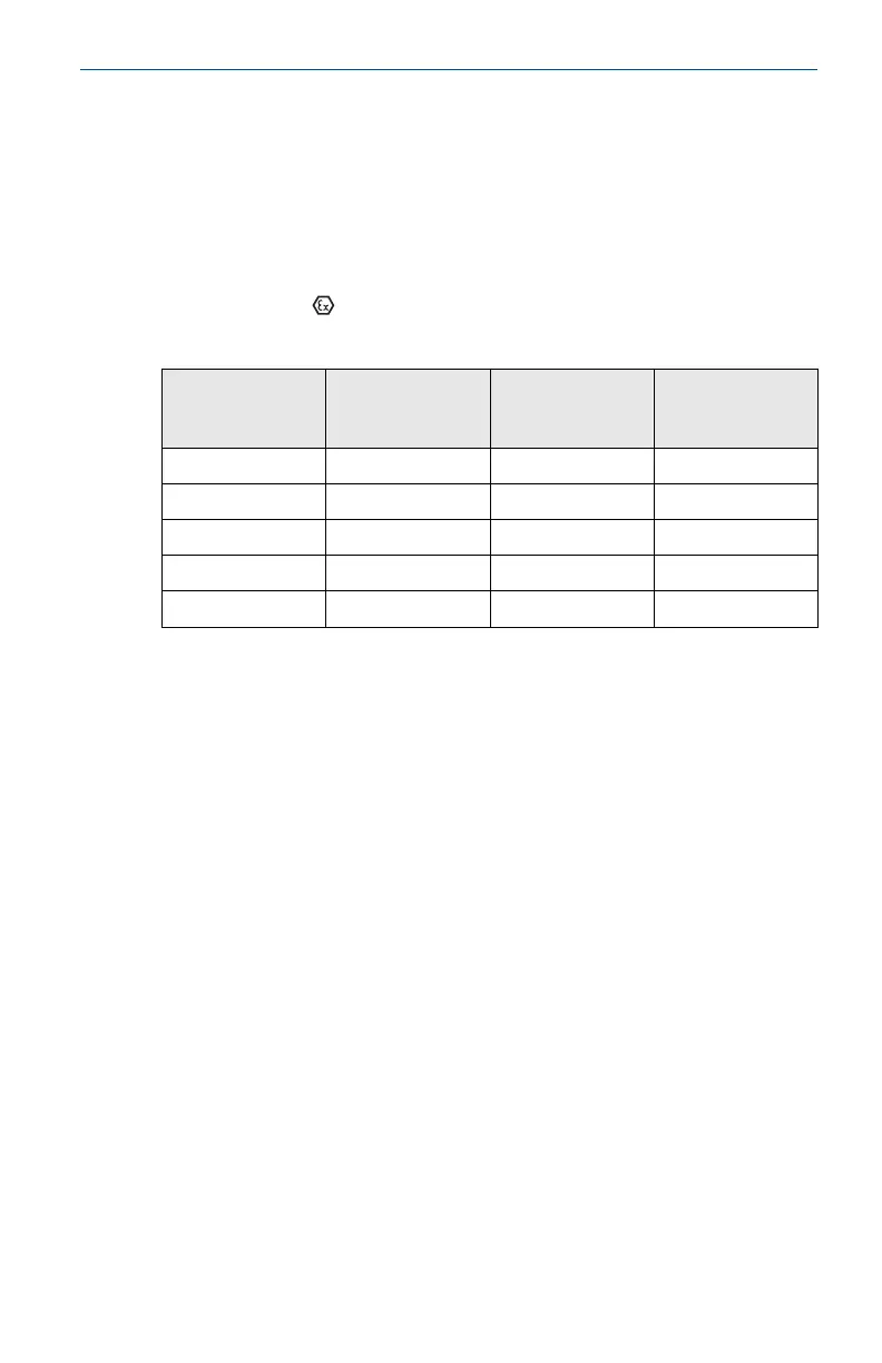
Sensor terminal
parameters
(input)
Switch terminal
parameters
(output)
Discrete Input
transmitter rev 2
output
Plunger Arrival
Transmitter
Output
U
O
= 6.6 V U
i
= 26 V U
O
= 6.6 V U
O
= 6.6 V
I
O
= 13.4 mA I
i
= 100 mA I
O
= 13.4 mA I
O
= 125 mA
P
O
= 21.8 mW P
i
= 0.65 W P
O
= 21.8 W P
O
= 202 mW
C
O
= 10.9 µF N/A Ci= 0.216 nF C
i
= 8.36 nF
L
O
= 25 µH N/A Li= 0 L
i
= 0
Special Conditions for Safe Use (X):
1. The surface resistivity of the antenna is greater than 1 GΩ. To avoid
electrostatic charge build-up, it must not be rubbed or cleaned with
solvents or dry cloth.
2. The Model 701PBKKF Power Module, MHM-89004 Blue Power
Module or Intelligent Power Module 71008 may be replaced in a
hazardous area. The Power Modules have a surface resistivity greater
than 1 GΩ and must be properly installed in the wireless device
enclosure. Care must be taken during transportation to and from the
point of installation to prevent electrostatic charge build-up.
8.9
International
8.9.1 I7 IECEx Intrinsic Safety
Certificate:
IECEx BAS 07.0082X
Standards:
IEC 60079-0: 2017, IEC 60079-11: 2011
Markings:
Ex ia IIC T4 Ga, T4(-60 °C ≤ T
a
≤ +70 °C)
Ex ia IIC T5 Ga, T5(-60 °C ≤ T
a
≤ +40 °C)
April 2021 Quick Start Guide
Quick Start Guide 45