5 Power
5.1 Power Input
The Mercury+ ST1 base board can be powered using one of the power input sources listed below:
• External power connection through J1701 barrel jack connector
• Internal power connection through J1700 connector
5.2 Power Generation Overview
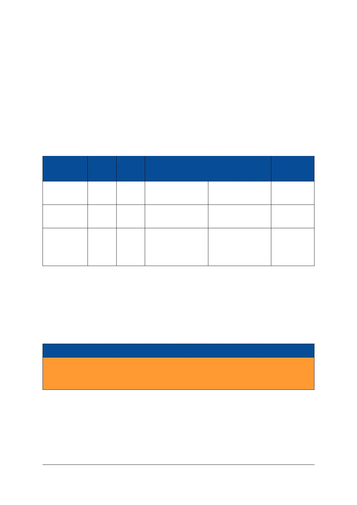
Table 18 describes the power supplies available on the base board.
Voltage Voltage Rated Voltage Enable Power Good
Supply Name Value Current Origin Signal Signal
VCC_5V 5.0 V 2 A Base board
(VCC_MAIN)
VCC_MAIN N/A
VCC_1V2 1.2 V 0.8 A Module
(VCC_3V3_MOD)
PWR_GOOD POR#_LOAD#
VCC_3V3_FTDI 3.3 V 0.15 A VCC_USBUB (primary
voltage source) or
VCC_3V3_MOD (sec-
ondary source)
VCC_USBUB /
VCC_3V3_MOD
N/A
Table 18: Generated Power Supplies
The 3.3 V voltage coming from the Mercury module (VCC_3V3_MOD) is sequenced on the base board
(VCC_3V3) using a load switch with PWR_GOOD as enable signal.
VCC_OUT_A, VCC_OUT_B and VCC_FMC_VIOB are voltage inputs to the Mercury+ ST1 base board coming
from the Mercury module, respectively from the FMC card.
VCC_OUT_C voltage, generated on the Mercury module, is accessible on test point TP301. This voltage
source is not used on the base board.
Warning!
The maximum available output current for each voltage supply depends on your design. Make sure
that the Mercury module I/O banks and the FMC cards do not draw more current than available on
the output of the DC/DC converter.
D-0000-456-001 26 / 48 Version 02, 23.07.2020
 Loading...