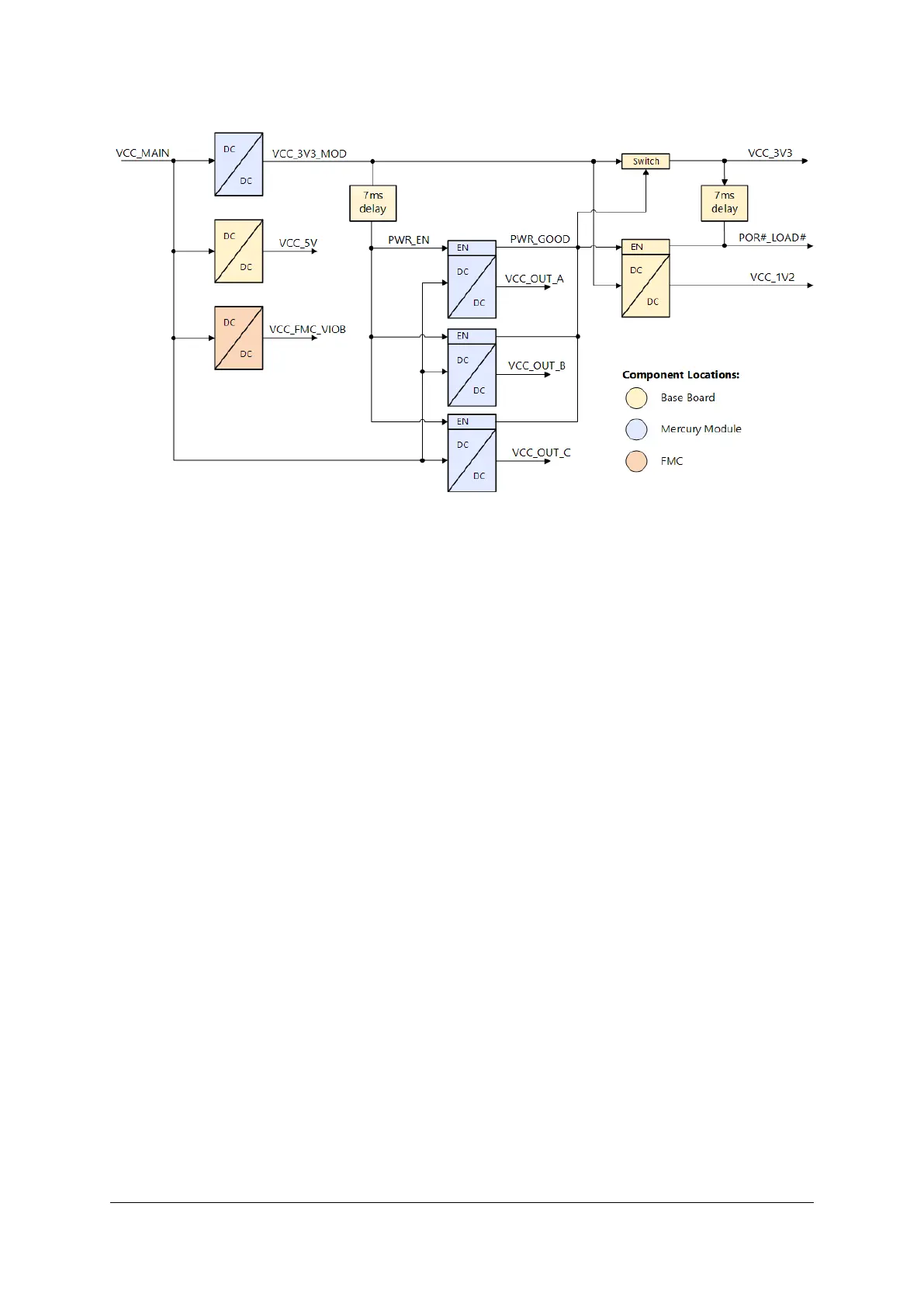
Figure 9: Power Sequence Overview
Please note that depending on the individual Mercury module, the voltage source for the DC/DC converters
for the voltage outputs (VCC_OUT_*) may be different than VCC_MAIN. Refer to the module’s user manual
for further information on power generation on the module.
5.5 Power Enable/Power Good
The power enable signal, PWR_EN, may be used to shut down the DC/DC converters on the Mercury mod-
ule - please refer to the module’s user manual for details on power generation.
On the Mercury+ ST1 base board the VCC_5V supply is always active and cannot be turned-off, except for
when removing the 12 V power input on the board.
The PWR_EN signal is released and no longer driven low if VCC_3V3_MOD signal is stable for 7 ms.
The PWR_GOOD signal is used for sequencing the 3.3 V voltage coming from the module - refer to Figures
8 and 9 for details.
5.6 I/O Voltage Selection
The I/O voltage selection jumpers are used to configure VCC_IO_A, VCC_IO_B and VCC_IO_C voltages
that power the I/O banks of the SoC/FPGA device on the Mercury module as well as the I/O voltage
VCC_FMC_ADJ for the FMC card.
The VCC_IO voltages are configurable by applying the required voltage from VCC_OUT_A, VCC_OUT_B,
VCC_FMC_VIOB, VCC_1V2 or VCC_3V3 pins. This can be done by setting the I/O selection jumpers accord-
ingly.
Tables 19, 20 and 21 describe the usage of jumpers. Please note the following:
• VCC_OUT is a supply output from the Mercury module. The value of the voltage depends on the
mounted Mercury module (Refer to the “Voltage Supply Outputs” Section in the Mercury module user
manual).
D-0000-456-001 28 / 48 Version 02, 23.07.2020
 Loading...