6.8 DisplayPort
The main link of the DisplayPort interface consists of two lanes, driven directly by the MGT signals on con-
nector B (pins B-13/17, B-21/25).
Lanes 0 and 1 are mapped directly to the transmitter side of the MGTs, while lane 2 and 3 are mapped to MGT
receivers. This allows a full duplex link between two individual Mercury+ ST1 base boards by connecting a
mini DisplayPort cable, for example for debugging or performance evaluation purposes.
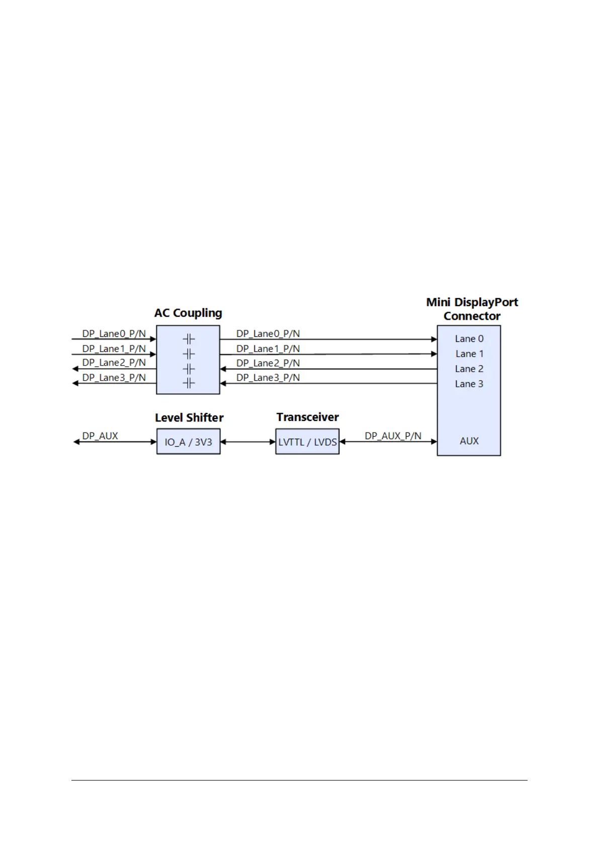
For the traditional DisplayPort applications the following connections are used: MGT transmitter lanes 0 and
1, along with an auxiliary channel (pins A-88/90/92) and a hot plug detect signal (pin A-94). The translation
between LVTTL and LVDS is done with a dedicated transceiver.
The supported DisplayPort standard is dependent on the connected Mercury module.
This interface is protected against electrostatic discharge by using TVS diodes.
Figure 15: Mini DisplayPort Connector with LVDS Transceiver
6.9 MIPI
Two MIPI (Mobile Industry Processor Interface) standard interfaces are available to the user. Default applica-
tion supports two CSI (Camera Serial Interface), MIPI0 and MIPI1, with two data lanes each. The form factor
allows to connect two low-cost Raspberry Pi cameras.
The MIPI pinout for both CSI interfaces has been checked to work optimally with the Mercury+ XU7, XU8 and
XU9 SoC modules. The pinout respects the RX rules indicated by the MIPI D-PHY IP core documentation [11].
The connector used for MIPI1 may optionally be connected to a two-lane capable display. To attach a
Raspberry Pi display, the lanes should be mapped according Table 28, column DSI mapping. Please note
that depending on the attached display the signal mapping may differ from the proposed permutations.
D-0000-456-001 39 / 48 Version 02, 23.07.2020
 Loading...