Board Reference / Pin I2C Net Name Comments
J200 / A-55 I2C_SCL_FPGA Signal is level shifted to 3.3 V
J200 / A-57 I2C_SDA_FPGA Signal is level shifted to 3.3 V
J200 / A-111 I2C_SCL
J200 / A-113 I2C_SDA
J200 / A-115 I2C_INT# Connected to Anios connectors and clock generator on the
base board
U505 / 2 I2C_SCL Connected to FTDI device when the FTDI mode setting is
[0,1]
U505 / 5, 11 I2C_SDA Connected to FTDI device when the FTDI mode setting is
[0,1]
Table 27: I2C Structure
6.7 HDMI
The Mercury+ ST1 base board supports HDMI 1.4b and 2.0b output signals. The display data channel (DDC)
for audio and video format recognition is wired to the I2C FPGA bus (pins A-55/57). The standard I2C bus
(A-111/113) is used for the redriver configuration.
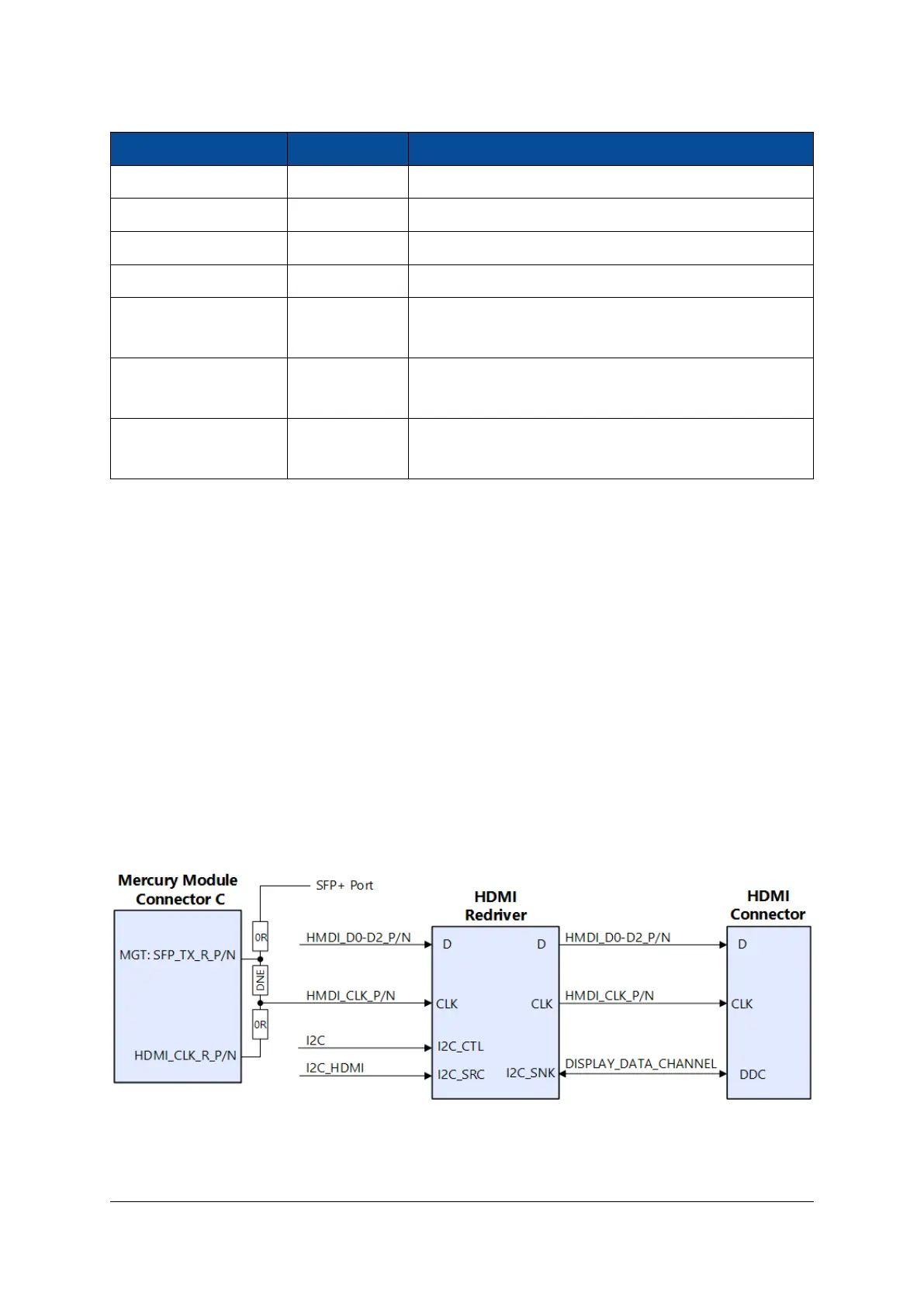
The three HDMI data lanes are routed to the Mercury module connector C (C-45/47, C-51/53, C-57/59) to
be connected to transceivers for modules having MGTs on these pins. By default the clock connection is
made to pins C-139/141. If the application requires having the clock mapped to the 4th MGT channel of the
same quad as the data lanes (pins C-63/65), it is possible to realize this connection by removing resistors
R310 - R313 and by populating R308 - R309. In this case, the SFP+ port is not available any longer.
The HDMI redriver equipped on the board performs pair deskew, therefore the configuration of three MGT
lanes and a TMDS clock (allowing for the additional SFP+ port) is supported.
This interface is protected against electrostatic discharge by using TVS diodes.
Figure 14: HDMI Connector with Redriver
D-0000-456-001 38 / 48 Version 02, 23.07.2020
 Loading...