List of Figures
1 Hardware Block Diagram . . . . . . . . . . . . . . . . . . . . . . . . . . . . . . . . . . . . . . . . 9
2 Product Label . . . . . . . . . . . . . . . . . . . . . . . . . . . . . . . . . . . . . . . . . . . . . . . 11
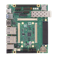
3 Board Top View . . . . . . . . . . . . . . . . . . . . . . . . . . . . . . . . . . . . . . . . . . . . . . 12
4 Board Bottom View . . . . . . . . . . . . . . . . . . . . . . . . . . . . . . . . . . . . . . . . . . . . 13
5 Board Top Assembly Drawing . . . . . . . . . . . . . . . . . . . . . . . . . . . . . . . . . . . . . . 14
6 Board Bottom Assembly Drawing . . . . . . . . . . . . . . . . . . . . . . . . . . . . . . . . . . . . 15
7 Board Dimensions . . . . . . . . . . . . . . . . . . . . . . . . . . . . . . . . . . . . . . . . . . . . 16
8 Maximum Power Budget Estimation . . . . . . . . . . . . . . . . . . . . . . . . . . . . . . . . . . 27
9 Power Sequence Overview . . . . . . . . . . . . . . . . . . . . . . . . . . . . . . . . . . . . . . . 28
10 VCC_IO Source Pins Positions - Power Pins . . . . . . . . . . . . . . . . . . . . . . . . . . . . . . 29
11 VCC_IO Jumper Positions - Pin Numbering and Configuration Example . . . . . . . . . . . . . 31
12 USB Connections Overview . . . . . . . . . . . . . . . . . . . . . . . . . . . . . . . . . . . . . . . 34
13 I2C Devices . . . . . . . . . . . . . . . . . . . . . . . . . . . . . . . . . . . . . . . . . . . . . . . . 37
14 HDMI Connector with Redriver . . . . . . . . . . . . . . . . . . . . . . . . . . . . . . . . . . . . . 38
15 Mini DisplayPort Connector with LVDS Transceiver . . . . . . . . . . . . . . . . . . . . . . . . . . 39
16 MIPI CSI/DSI Interface with Zynq UltraScale+ Modules . . . . . . . . . . . . . . . . . . . . . . . 40
17 MIPI CSI Interface with Zynq-7000/7-Series Modules . . . . . . . . . . . . . . . . . . . . . . . . 41
18 Clock Architecture Overview . . . . . . . . . . . . . . . . . . . . . . . . . . . . . . . . . . . . . . 42
List of Tables
1 Base Board Features . . . . . . . . . . . . . . . . . . . . . . . . . . . . . . . . . . . . . . . . . . . 10
2 Standard Base Board Configuration . . . . . . . . . . . . . . . . . . . . . . . . . . . . . . . . . . 10
3 Article Numbers and Article Codes . . . . . . . . . . . . . . . . . . . . . . . . . . . . . . . . . . . 11
4 Mechanical Data . . . . . . . . . . . . . . . . . . . . . . . . . . . . . . . . . . . . . . . . . . . . . 17
5 List of Mechanical Components . . . . . . . . . . . . . . . . . . . . . . . . . . . . . . . . . . . . . 17
6 J1701 - External Power Connector . . . . . . . . . . . . . . . . . . . . . . . . . . . . . . . . . . . . 18
7 J1701 - External Power Connector Type . . . . . . . . . . . . . . . . . . . . . . . . . . . . . . . . 18
8 J1700 - Internal Power Connector . . . . . . . . . . . . . . . . . . . . . . . . . . . . . . . . . . . . 18
9 J1700 - Internal Power Connector Type . . . . . . . . . . . . . . . . . . . . . . . . . . . . . . . . 18
10 J1601 - Fan Connector . . . . . . . . . . . . . . . . . . . . . . . . . . . . . . . . . . . . . . . . . . 19
11 J1601 - Fan Connector Type . . . . . . . . . . . . . . . . . . . . . . . . . . . . . . . . . . . . . . . 19
12 Mating Part for the Fan Connector . . . . . . . . . . . . . . . . . . . . . . . . . . . . . . . . . . . 19
13 J1400 - FMC HPC Connector Type . . . . . . . . . . . . . . . . . . . . . . . . . . . . . . . . . . . 21
14 Available I/Os on the FMC Connector . . . . . . . . . . . . . . . . . . . . . . . . . . . . . . . . . 22
15 J1506 - FPGA TAG Connector . . . . . . . . . . . . . . . . . . . . . . . . . . . . . . . . . . . . . . 23
16 J1600 - Battery Holder Type . . . . . . . . . . . . . . . . . . . . . . . . . . . . . . . . . . . . . . . 24
17 J1502 - FPGA JTAG Connector . . . . . . . . . . . . . . . . . . . . . . . . . . . . . . . . . . . . . . 25
18 Generated Power Supplies . . . . . . . . . . . . . . . . . . . . . . . . . . . . . . . . . . . . . . . . 26
19 Jumper Settings VCC_IO_A . . . . . . . . . . . . . . . . . . . . . . . . . . . . . . . . . . . . . . . 29
20 Jumper Settings VCC_IO_B . . . . . . . . . . . . . . . . . . . . . . . . . . . . . . . . . . . . . . . 30
21 Jumper Settings VCC_IO_C . . . . . . . . . . . . . . . . . . . . . . . . . . . . . . . . . . . . . . . 30
22 Board LEDs . . . . . . . . . . . . . . . . . . . . . . . . . . . . . . . . . . . . . . . . . . . . . . . . 32
23 Board Buttons . . . . . . . . . . . . . . . . . . . . . . . . . . . . . . . . . . . . . . . . . . . . . . . 32
24 Configuration Switch . . . . . . . . . . . . . . . . . . . . . . . . . . . . . . . . . . . . . . . . . . 33
25 USB Connection Table . . . . . . . . . . . . . . . . . . . . . . . . . . . . . . . . . . . . . . . . . . 35
26 FTDI Configuration Settings - Port B . . . . . . . . . . . . . . . . . . . . . . . . . . . . . . . . . . 36
27 I2C Structure . . . . . . . . . . . . . . . . . . . . . . . . . . . . . . . . . . . . . . . . . . . . . . . . 38
28 MIPI Connector 1 CSI / DSI Signal Mapping - Rasperry Pi Display Lane Mapping . . . . . . . . 40
29 MIPI I2C Bus Selection and Connectivity Options . . . . . . . . . . . . . . . . . . . . . . . . . . . 40
30 MIPI Connector 0 CSI - Hardware Changes for older FPGA Families . . . . . . . . . . . . . . . . 41
31 MIPI Connector 1 CSI - Hardware Changes for older FPGA Families . . . . . . . . . . . . . . . . 41
32 Clock Generator Type . . . . . . . . . . . . . . . . . . . . . . . . . . . . . . . . . . . . . . . . . . 42
33 Absolute Maximum Ratings . . . . . . . . . . . . . . . . . . . . . . . . . . . . . . . . . . . . . . . 43
D-0000-456-001 45 / 48 Version 02, 23.07.2020
 Loading...