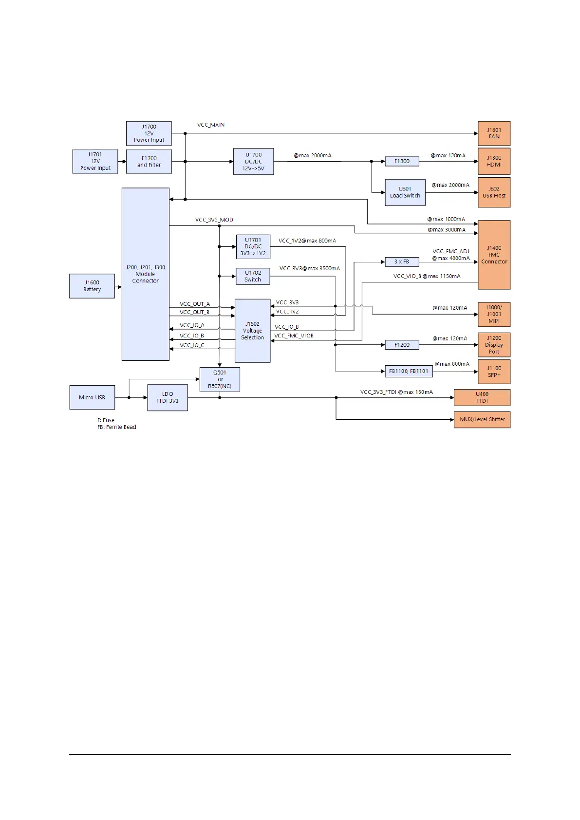
5.3 Maximum Power Budget
Figure 8: Maximum Power Budget Estimation
5.4 Power Sequencing
The Mercury+ ST1 base board will only power up when a Mercury module is properly connected to its socket.
As soon as the main voltage (VCC_MAIN) is applied, VCC_5V will start up and the mated Mercury module
will drive up a 3.3 V supply (VCC_3V3_MOD). When this voltage becomes available on the base board, the
PWR_EN signal is set to high (after a delay of 7 ms), enabling the I/O supplies on the module.
When these I/O voltages are stable, the PWR_GOOD signal goes high and the sequenced on-board 3.3 V
(VCC_3V3) and 1.2 V (VCC_1V2) power domains are switched on.
D-0000-456-001 27 / 48 Version 02, 23.07.2020
 Loading...