6.3 DIP Switches
There is a 4-bit configuration switch on the Mercury+ ST1 base board. Table 24 describe its function; the
factory default is marked in bold.
Warning!
Please note that the DIP switches must be configured according to the connectivity requirements. The
factory default configuration does not implicitly indicate a valid configuration. The DIP switches may
require different settings depending on the equipped module.
For details on the board configuration, refer to the Mercury+ ST1 Base Board User Schematics [4].
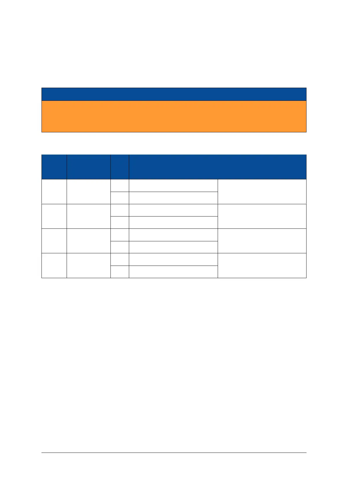
DIP
Switch Signal Name Pos. Effect Comments
CFG 1 BOOT_MODE0
OFF BOOT_MODE0 is set to 1 Refer to the Mercury module
ON BOOT_MODE0 is set to 0 user manual
CFG 2 BOOT_MODE1
OFF BOOT_MODE1 is set to 1 Refer to the Mercury module
ON BOOT_MODE1 is set to 0 user manual
CFG 3 USB_MODE0
OFF USB_MODE0 is set to 1
Refer to Figure 12
ON USB_MODE0 is set to 0
CFG 4 USB_MODE1
OFF USB_MODE1 is set to 1
Refer to Figure 12
ON USB_MODE1 is set to 0
Table 24: Configuration Switch
6.4 Ethernet
The Mercury+ ST1 base board is equipped with two Gigabit Ethernet ports, configured according to the
capabilities of the mounted module.
The RJ45 connector with integrated magnetics is equipped on the base board, while the Ethernet PHY is
equipped on the Mercury module.
D-0000-456-001 33 / 48 Version 02, 23.07.2020
 Loading...