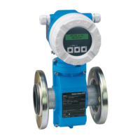
Deltabar S
10 Endress+Hauser
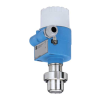
The operating buttons located externally on the device work on the Hall sensor principle. This guarantees the
following advantages:
• Complete protection against environmental influences such as moisture and contamination
• Simple operation without any tools
• No wear
Note!
With the "External push buttons" option, a display module is always purchased. → See also page 53 ff, feature
20 "Electronics, communication, display, operation".
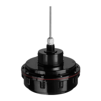
Operating keys and elements located internally on the electronic insert
HistoROM
®
/M-DAT
(optional)
HistoROM
®
/M-DAT is a memory module, which is attached to the electronic insert. The HistoROM
®
/M-DAT
can be retrofitted into an existing transmitter.
Your benefits
• Quick and safe commissioning of the same measuring points by copying the configuration data of one
transmitter to another transmitter
• Reliable process monitoring due to cyclical recording of pressure and sensor temperature measured values
• Simple diagnosis by recording events such as alarms, maximum indicators, counters for measuring
excursions outside user-specified pressure and temperature limits
• Analysis and graphic evaluation of the events and process parameters via ToF Tool (contained in scope of
supply)
HistoROM
®
/M-DAT can be ordered via feature 100 "Additional options 1" or feature 110 "Additional options
2". → See also page 53 ff.
P01-xxxxxxxx-19-xx-xx-xx-074
Electronic insert HART
1 Operating keys
2 Green LED to indicate acceptance of value
3 Slot for optional display
4 Slot for optional HistoROM
®
/
M-DAT
5 DIP-switch for locking/unlocking measured-
value parameters
6 DIP-switch for damping on/off
P01-xxxxxxxx-19-xx-xx-xx-075
Electronic insert PROFIBUS PA
1 Green LED to indicate acceptance of value
2 Key for position calibration
3 Slot for optional display
4 Slot for optional HistoROM
®
/
M-DAT
5 DIP-switch for hardware address
6 DIP-switch without function
7 DIP-switch for locking/unlocking measured-
value parameters
P01-xxxxxxxx-19-xx-xx-xx-054
Electronic insert Foundation Fieldbus
1 Green LED to indicate acceptance of value
2 Key for position calibration
3 Slot for optional display
4 Slot for optional HistoROM
®
/
M-DAT
5 DIP-switch for simulation mode
6 DIP-switch for locking/unlocking measured-
value parameters
t
Display
Damping
off
on
[]
Sensor
Histo
ROM
21
PC
onoff
1
2
3
4
5
6
on on
off off
12
3
4
5
678
SW
HW
Address
0%
Zero
Histo
ROM
Sensor
Display
21
PC
21
CKON
34 5 678
SDA08
01
1
2
3
on
off
1
2
4
5
7
6
on
off
HW
0%
Zero
Histo
ROM
Sensor
Display
21
PC
01
F
OUNDATION
Simulation
1
2
Simulation
on
off
1
2
3
4
5
6
 Loading...