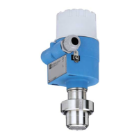
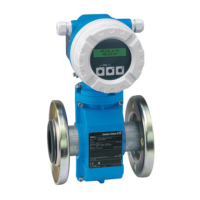
Deltabar S
16 Endress+Hauser
Measuring 4 to 20 mA test signal
A 4 to 20 mA signal may be measured via the positive and test terminal without interrupting the measurement.
The minimum supply voltage of the device can be reduced by simply changing the position of the jumper. As
a result, operation is also possible with lower voltage sources. Observe the position of the jumper in accordance
with the following table.
Supply voltage Note!
• When using the measuring device in hazardous areas, installation must comply with the corresponding
national standards and regulations and the Safety Instructions (XAs) or Installation or Control Drawings
(ZDs).
• All explosion protection data are given in separate documentation which is available upon request. The Ex
documentation is supplied as standard with all devices approved for use in explosion hazardous areas. → See
also page 67, sections "Safety Instructions" and "Installation/Control drawing".
4 to 20 mA HART
• Version for non-hazardous areas, jumper for 4 to 20 mA test signal in "Standard" position: 10.5 to 45 V DC
• Version for non-hazardous areas, jumper for 4 to 20 mA test signal in "Test" position:
11.5 to 45 V DC
PROFIBUS-PA
Version for non-hazardous areas: 9 to 32 V DC
Foundation Fieldbus
Version for non-hazardous areas: 9 to 32 V DC
Current consumption
• PROFIBUS-PA: 11 mA ± 1 mA, switch-on current corresponds to table 4, IEC 61158-2
• Foundation Fieldbus: 11 mA ± 1 mA, switch-on current corresponds to table 4, IEC 61158-2
Cable entry → See also page 53 ff , feature 30 "Housing, Cable entry, Protection".
Cable specification
• Endress+Hauser recommends using shielded, twisted-pair two-wire cables.
• Terminals for wire cross-sections 0.5 to 2.5 mm
2
• Cable external diameter: 5 to 10 mm
Residual ripple Without influence on 4 to 20 mA signal up to ± 5 % residual ripple within the permitted voltage range
[according to HART hardware specification HCF_SPEC-54 (DIN IEC 60381-1)]
Influence of power supply ≤ 0.0006% of URL/1 V
Jumper position for test signal Description
– Measuring 4 to 20 mA test signal via plus and test terminal:
not possible.
– Delivery status
– minimum supply voltage: 10.5 V DC
– Measuring 4 to 20 mA test signal via plus and test terminal:
possible. (Thus, the output current can be measured without
interruption via the diode.)
– minimum supply voltage: 11.5 V DC
Test
Test
 Loading...