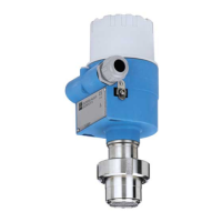
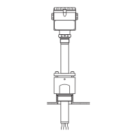
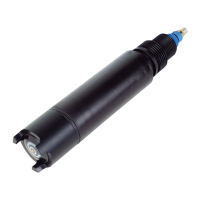
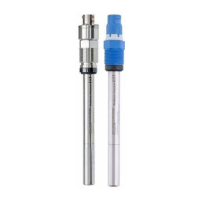
Deltabar S
14 Endress+Hauser
Output
Output signal • 4 to 20 mA with superimposed digital communication protocol HART, 2-wire
• Digital communication signal PROFIBUS-PA (Profile 3.0)
• Digital communication signal Foundation Fieldbus
Signal on alarm
• 4 to 20 mA HART
Options:
– Max. alarm*: can be set from 21 to 23 mA
– Keep measured value: last measured value is kept
– Min. alarm: 3.6 mA
* Factory setting: 22 mA
• PROFIBUS-PA: can be set in the Analog Input block, options: good, bad, uncertain
• Foundation Fieldbus: can be set, options: good, bad, uncertain
Load – 4 to 20 mA HART
P01-xMD7xxxx-05-xx-xx-xx-000
Load diagram, observe the position of the jumper and the explosion protection (→ See also page 16, section "Measuring 4
to 20 mA test signal".)
1 Jumper for 4 to 20 mA test signal inserted in "Standard" position
2 Jumper for 4 to 20 mA test signal inserted in "Test" position
3 Supply voltage 10.5 (11.5) to 30 V DC for EEx ia, 1/2 D, 1 GD, 1/2 GD, FM IS and CSA IS
4 Supply voltage 10.5 (11.5) to 45 V DC for device for non-hazardous areas, 1/3 D, EEx d, EEx nA, FM XP, FM DIP,
FM NI, CSA XP and CSA Dust-Ex
R
Lmax
Maximum load resistance
U Supply voltage
Note!
When operating via a handheld terminal or via PC with an operating program, a minimum communication
resistance of 250 Ω must exist within the loop.
Resolution
• Current output: 1 µA
• Display: can be set (setting at the factory: presentation of the maximum accuracy of the transmitter)
Reading cycle
• HART commands: on average 3 to 4 per second
• PROFIBUS-PA:
– cyclic: on average 100/s
– acyclic: on average 20/s
• Foundation Fieldbus:
– cyclic up to 5/s, dependent on the number and type of function blocks used in a closed-control loop
– acyclic: 10/s
U – 10.5 V
R
L
max
23 mA
£
30
20
10.5
U
[V]
40 45
1282
1500
847
413
[]W
R
L
max
30
20
11.5
U
[V]
40 45
1239
1456
804
369
[]W
R
L
max
TestTest
U – 11.5 V
R
L
max
23 mA
£
2
3
3
4
4
1
 Loading...
