Deltabar S
Endress+Hauser 31
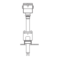
Process connection FMD 76
(with ceramic measuring
diaphragms)
EN/DIN flanges, connection dimensions as per EN 1092-1/DIN 2527
P01-FMD76xxx-06-09-xx-xx-000
Process connection FMD 76, high-pressure side: EN/DIN flange (see table below),
low-pressure side: connection 1/4"-18 NPT
H Device height → see page 33, section "Device height H, devices with flange"
h Height of the device without flange thickness b
1.63”
(41.3)
1.61”
(41)
k
D
b
H
ø1.81”
(46)
g
2
h
7/16”-20 UNF
1/4”-18 NPT
Flange Bolt holes
Version Material Nominal
diameter
Shape Nominal
pressure
Diameter Thickness Quantity Diameter Hole circle Flange
weight
1
Db g
2
k
[mm] [mm] [mm] [mm] [kg]
B AISI 316L DN 80 A PN 25/40 200 24 8 18 160 5.3
DECTFE
2
DN 80 – PN 10-40 200 24 8 18 160 5.3
E Alloy C276 DN 80 A PN 10-40 200 24 8 18 160 6
F AISI 316L DN 100 A PN 10/16 220 22 8 18 180 6
G AISI 316L DN 100 A PN 25-40 235 26 8 22 190 8
HECTFE
2
DN 100 – PN 25-40 235 26 8 22 190 8
J Alloy C276 DN 100 A PN 25-40 235 26 8 22 190 9
LECTFE
2
DN 100 – PN 10-16 220 22 8 18 180 6
M Alloy C276 DN 100 A PN 10-16 220 22 8 18 180 6.8
1) for housing weight see page 44
2) ECTFE coating on AISI 316L.
When operating in hazardous area, avoid electrostatic charge of the plastic surfaces.
 Loading...