Deltabar S
32 Endress+Hauser
ANSI flanges, connection dimensions as per ANSI B 16.5, raised face RF and
JIS flanges, connection dimensions as per B 2210, raised face RF
P01-FMD76xxx-06-09-xx-xx-001
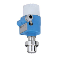
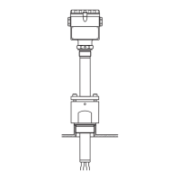
Process connection FMD 76, high-pressure side: ANSI or JIS flange (see table below),
low-pressure side: connection 1/4"-18 NPT
H Device height → see page 33, section "Device height H, devices with flange"
h Height of the device without flange thickness b
41.3
41
(1.61”)
k
g
b
H
1.6
(0.06”)
(1.63”)
ø46
(ø1.81”)
g
2
D
h
7/16”-20 UNF
1/4”-18 NPT
Flange Bolt holes
Version Material Nominal
diameter
Class/
Nominal
pressure
1
Diameter Thickness Raised face Quantity Diameter Hole circle Flange
weight
2
Dbg g
2
k
inch in
(mm)
in
(mm)
in
(mm)
in
(mm)
in
(mm)
lb
(kg)
ANSI flange
P AISI 316/
316L
3
3 150
lb./sq.in
7.5
(190.5)
0.94
(23.9)
5
(127)
40.75
(19.1)
6
(152.4)
11 (4.9)
RECTFE
4
11 (4.9)
S Alloy C276 12 (5.5)
T AISI 316/
316L
3
4 150
lb./sq.in
9
(228.5)
0.94
(23.9)
6.19
(157.2)
80.75
(19.1)
7.5
(190.5)
16 (7.1)
UECTFE
4
16 (7.1)
V Alloy C276 18 (8)
W AISI 316/
316L
3
4 300
lb./sq.in
10
(254)
1.25
(
31.8)
6.19
(
157.2)
80.88
(
22.4)
7.88
(
200.2)
26 (11.7)
JIS flange
1 AISI 316L 80 10 K (185)
7.32
(18)
0.71
(127)
5
8 (19.1)
0.75
(150)
5.9
7 (3.3)
3 Alloy C276 8 (3.7)
4 AISI 316L 100 10 K (210)
8.27
(18)
0.71
(151)
5.95
8 (19.1)
0.75
(175)
6.89
10 (4.4)
1) For ANSI flange Class in lb./sq.in and JIS flange Nominal pressure in K
2) For housing weight see page 44
3) Combination of AISI 316 for required pressure resistance and AISI 316L for required chemical resistance (dual rated)
4) ECTFE coating on AISI 316L.
When operating in hazardous area, avoid electrostatic charge of the plastic surfaces.
 Loading...