Deltabar S
34 Endress+Hauser
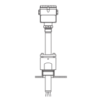
Process connections
FMD 77 (with metallic
measuring diaphragms), high-
pressure side
Note!
Specifications for the "T
K
Ambient" and "T
K
Process" are listed in the following tables. These temperature
coefficients apply to silicone oil and the membrane material AISI 316L. For other filling oils, this temperature
coefficient must be multiplied by the T
K
correction factor of the corresponding filling oil. For the T
K
correction
factors, see also page 46, section "Diaphragm seal filling oils".
EN/DIN flanges, connections as per EN 1092-1/DIN 2527
P01-FMD77xxx-06-09-xx-xx-002
Process connection FMD 77, high-pressure side EN/DIN flange with and without extended diaphragm seal, material AISI
316L
H Device height see page 36, → section "Device height H"
h Height of the device without flange thickness b
L
d
3
k
D
b
H
h
d
M
g
2
Flange Bolt holes Diaphragm seal
Ver-
sion
No-
minal
dia-
meter
Nominal
pressure
Shape
1
Dia-
meter
Thick-
ness
Exten-
sion
length
Exten-
sion dia-
meter
Quan-
tity
Dia-
meter
Hole
circle
Dia-
phragm
dia-
meter
T
K
Am-
bient
T
K
Pro-
cess
Flange
weight
2
DbLd
3
g
2
kd
M
[mm] [mm] [mm] [mm] [mm] [mm] [mm] [mbar/10 K] [kg]
A DN 50 PN 25/40 A 165 20 – – 4 18 125 52 +3.02 +1.15 3.0
B DN 80 PN 25/40 A 200 24 – – 8 18 160 80 +0.33 +0.20 5.2
C DN 80 PN 10-40 B1 (D) 200 24 50 76 8 18 160 72 +0.23 +0.11 6.2
100 6.7
200 7.8
F DN 100 PN 10/16 A 220 22 – – 8 18 180 80 +0.81 +0.46 4.8
G DN 100 PN 25-40 A 235 26 – – 8 22 190 80 +0.81 +0.46 6.7
1) Designation as per DIN 2527 in brackets
2) For housing weight see page 44
 Loading...